Motor

a motor and motor shaft technology, applied in the field of motors, can solve the problems of low structural intensity of the core block, noise and vibration of the motor, and high production cost of conventional motors, and achieve the effect of reducing the cogging torqu

Active Publication Date: 2008-09-11
LG ELECTRONICS INC
View PDF11 Cites 25 Cited by
  • Summary
  • Abstract
  • Description
  • Claims
  • Application Information

AI Technical Summary

Benefits of technology

[0013]Therefore, one advantage of the embodiments of the present disclosure is to provide a motor capable of reducing a cogging torque.
[0014]Another advantage is to provide a motor capable of being rotated with a high speed by preventing a rotor from being deformed or damaged.
[0016]According to another embodiment, there is provided a motor, comprising: a shaft; a plurality of core blocks coupled to the shaft; and a plurality of permanent magnets inserted into each of the core blocks, wherein the core block comprises: a core sheet having a flux barrier for preventing a leakage of a magnetic flux; and an anti-deformation rib for preventing the flux barrier from being deformed.
[0017]According to still another embodiment, there is provided a motor, comprising: a shaft; a plurality of core blocks coupled to the shaft; a plurality of permanent magnets inserted into each of the core blocks; and an aligning unit coaxial with the shaft and disposed between the shaft and the core blocks, for arranging the permanent magnets with a phase difference from each other in a rotation direction, wherein the core block comprises: a core sheet having a flux barrier for preventing a leakage of a magnetic flux; and an anti-deformation rib for preventing the flux barrier from being deformed.

Problems solved by technology

The cogging torque may cause noise and vibration of the motor.
However, the conventional motor has high production costs at least due to the skew process by which a plurality of the core blocks are laminated to each other so that the permanent magnets can be disposed in a zigzag form, and due to the assembly of the core blocks to each other using one or more rivets.
Accordingly, a structural intensity of the core block is low, and thus the bridge is deformed or damaged due to a strong centrifugal force when the rotor is rotated with a high speed.

Method used


Image

  • Motor
  • Motor
  • Motor

Examples


Embodiment Construction

[0027]Reference will now be made in detail to embodiments of the present disclosure, examples of which are illustrated in the accompanying drawings.

[0028]Hereinafter, a motor according to the present invention will be explained.

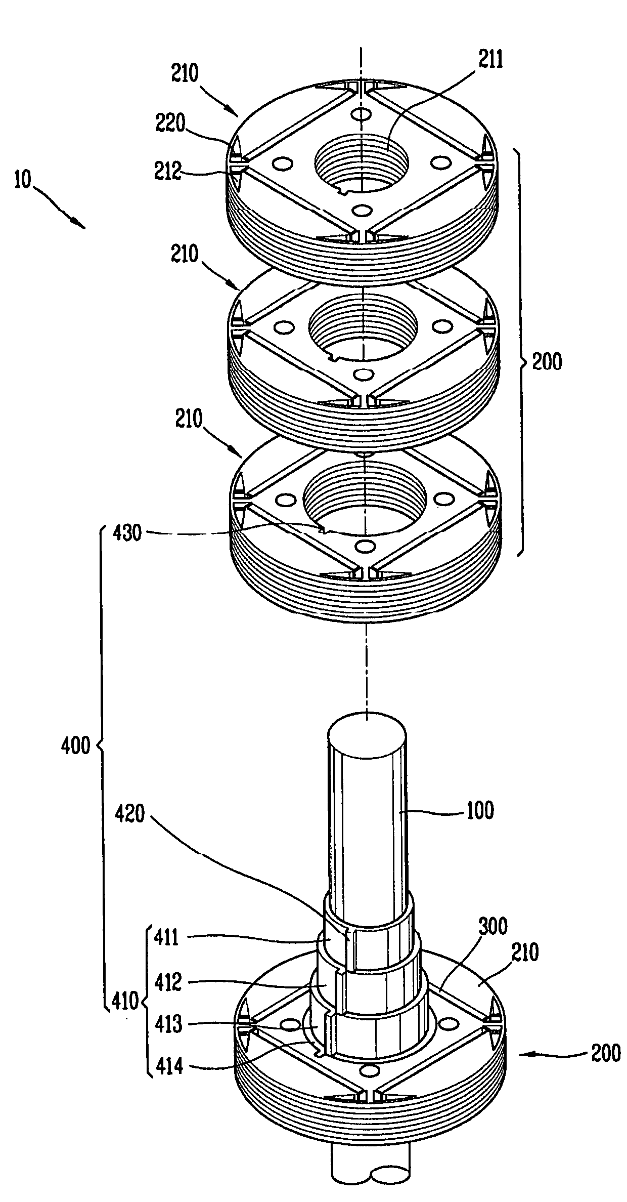
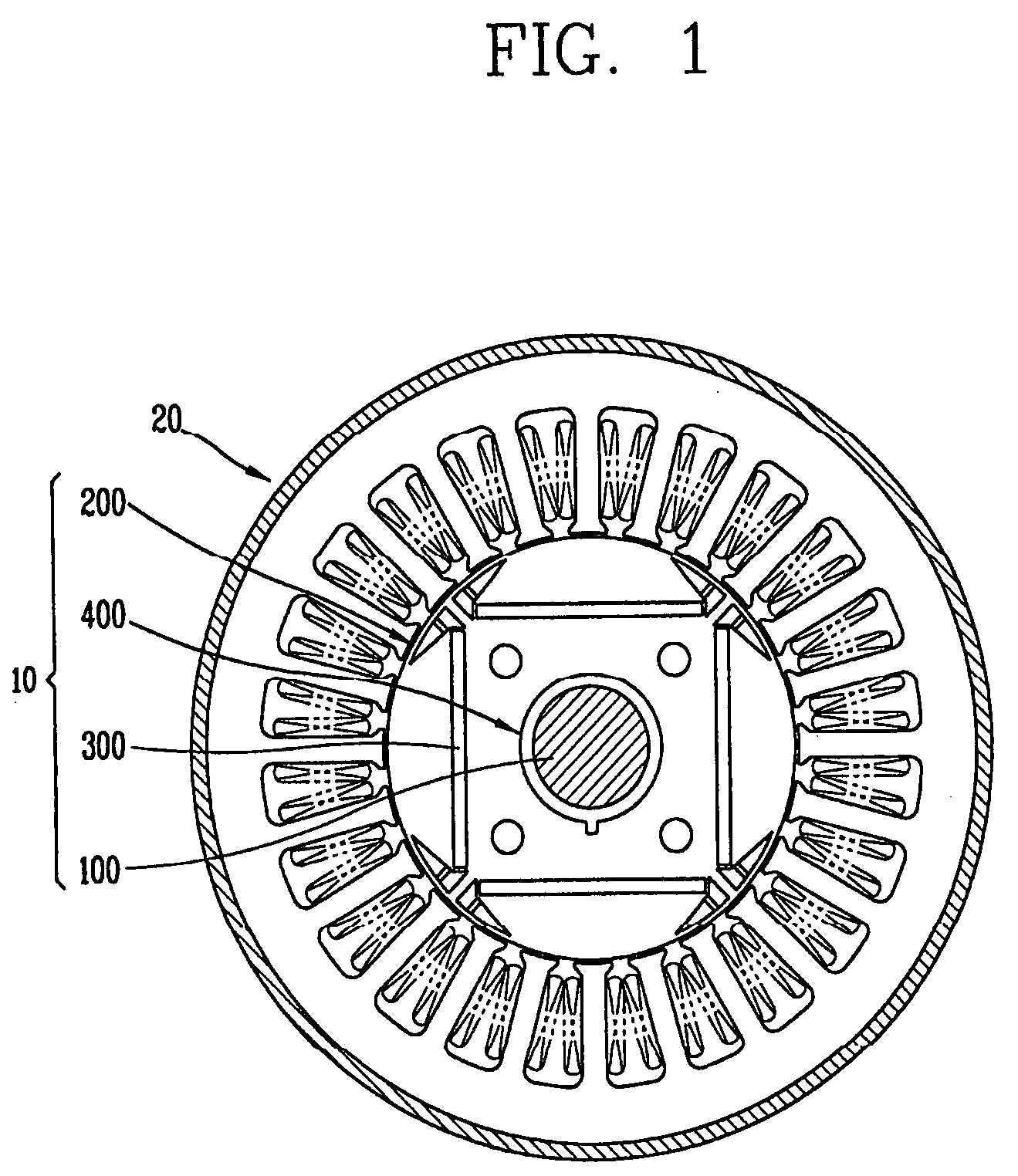
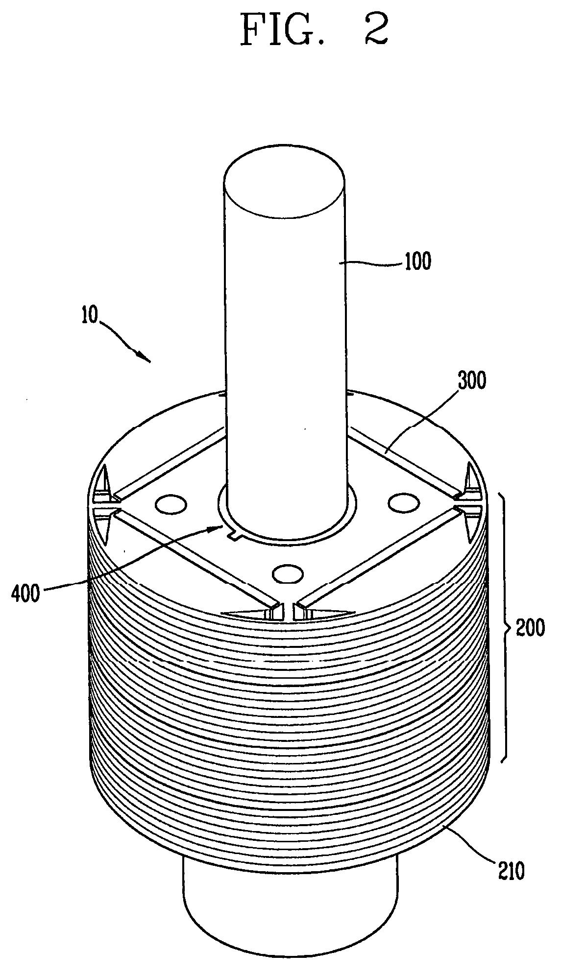
[0029]FIG. 1 is a view showing a motor according to a first embodiment of the present invention, and FIG. 2 is a perspective view showing a rotor of the motor of FIG. 1.

[0030]Referring to FIGS. 1 and 2, the motor according to a first embodiment of the present invention comprises a rotor 10 and a stator 20. The rotor 10 includes a shaft 100; a plurality of core blocks 200 coupled to the shaft 100; a plurality of permanent magnets 300 inserted into each of the core blocks; and an aligning unit 400 coaxial with the shaft 100 and disposed between the shaft 100 and the core blocks 200, for arranging the permanent magnets 300 with a phase difference from each other in a rotation direction.

[0031]The shaft 100 may have a bar shape and a circular cross-section. A plur...


PUM


Abstract

A motor that reduces a cogging torque and rotates at a high speed is presented. The motor comprises: a shaft, a plurality of core blocks coupled to the shaft, a plurality of permanent magnets inserted into each of the core blocks, and an aligning unit, coaxial with the shaft, and disposed between the shaft and the core blocks. The core block includes a plurality of core sheets each having at least a pair of flux barriers formed to be symmetrical to each other about a line of symmetry. A first rib lies along the line of symmetry and a separate anti-deformation rib is positioned within each of the pair of flux barriers. Accordingly, a skew process for a rotor is facilitated. An anti-deformation rib within the flux barrier provides structural integrity for the core block. Accordingly, when the rotor is rotated with a high speed, a bridge is prevented from being deformed.

Description

[0001]This application claims priority to Korean Application No. 10-2007-0023205, filed on Mar. 8, 2007, which is expressly incorporated by reference herein in its entirety.BACKGROUND[0002]1. Field of the Disclosure[0003]The present disclosure relates to a motor, and more particularly, to a motor capable of reducing a cogging torque and being rotated with a high speed.[0004]2. Description of the Related Art[0005]A motor is a device for converting electric energy into mechanical energy, and is used in all kinds of devices as a driving source.[0006]Motors are generally identified as either a direct current motor or an alternating current motor, according to a power source. The alternating current motor is classified into an induction motor, a synchronous motor, and a commutator motor.[0007]A rotor of the synchronous motor includes a shaft, a plurality of core blocks coupled to the shaft, and a permanent magnet inserted into each of the core blocks.[0008]When power is supplied to a sta...

Claims


Application Information

Patent Timeline
Patent Type & Authority Applications(United States)
IPC IPC(8): H02K21/12
CPCH02K29/03H02K1/276H02K1/27
Inventor LEE, SUNG-HOCHOI, JAE-HAKPARK, JIN-SOO
Owner LG ELECTRONICS INC
Why Eureka
Try Eureka