Mounting structure with heat sink for electronic component and female securing member for same

a technology for mounting structures and electronic components, which is applied in the direction of cooling/ventilation/heating modifications, semiconductor/solid-state device details, and semiconductor devices. it can solve the problems of low heat transmission rubber thermal conductivity, and high cost of heat sink securing structures, so as to reduce the number of securing components, the effect of safe and reliable securing of heat sinks

Active Publication Date: 2008-09-11
NEC CORP
View PDF6 Cites 10 Cited by
  • Summary
  • Abstract
  • Description
  • Claims
  • Application Information

AI Technical Summary

Benefits of technology

[0015]In view of the above, it is an object of the present invention to provide a mounting structure for electronic components and securing members which are capable of readily accommodating variations in the height of electronic components at a time of mounting, of securing a heat sink safely and reliably, of reducing securing component counts, and of improving dissipation characteristics.

Problems solved by technology

However, thermal conductivity of the heat transmission rubber is low and highly-priced, which causes high costs of the heat sink securing structure, therefore, conventionally, the compression springs are generally used.
However, the above related mounting structure has a problem.
That is, the height accommodating tool to secure the heat sink 3 to the printed circuit board 1 is made up of the male screws 7, the shafts (female screws) 5, the compression coil springs 10, and the washers 9 and, therefore, component counts are large, many attaching man-hours are required, thus causing complicated mounting processes.
Additionally, the related mounting structure for the heat sink has another problem.
That is, each of the male screws 7 and / or compression coil springs 10 spring out therefrom, a wind path F (FIG. 6) of a fan (not shown) is stopped up, thus resulting in lowering of the dissipation efficiency.

Method used


Image

  • Mounting structure with heat sink for electronic component and female securing member for same
  • Mounting structure with heat sink for electronic component and female securing member for same
  • Mounting structure with heat sink for electronic component and female securing member for same

Examples


Embodiment Construction

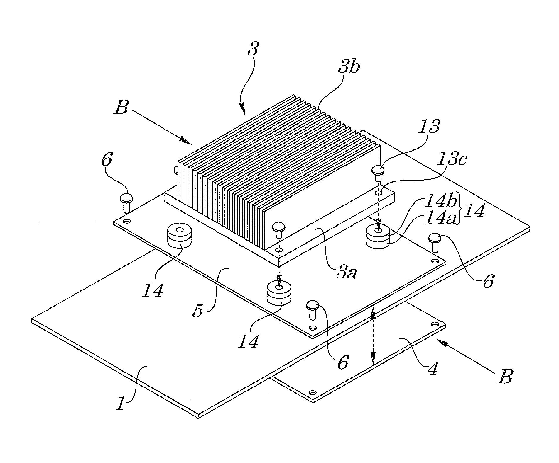
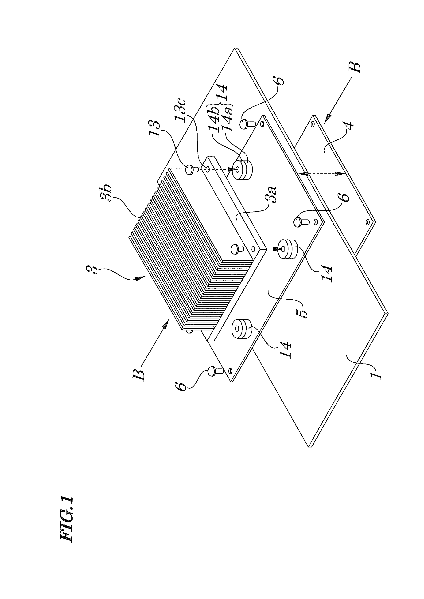
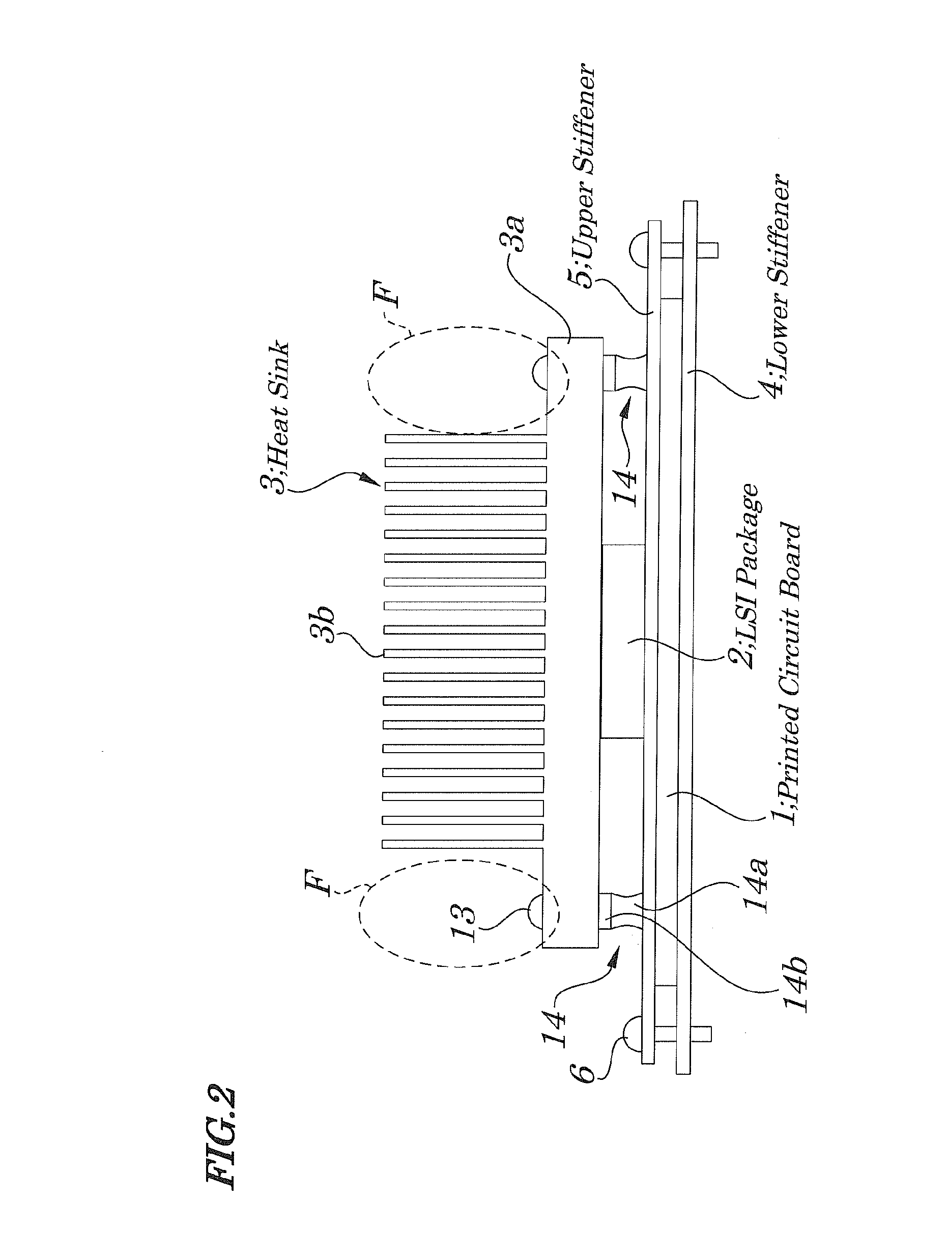
[0040]Best modes of carrying out the present invention will be described in further detail using various exemplary embodiments with reference to the accompanying drawings. The mounting structure of the present invention includes a printed circuit board 1 on which LSI packages (electronic components) are mounted, a lower stiffener (first supporting member) 4 on which the printed circuit board is disposed, an upper stiffener (second supporting member) 5 disposed on an upper surface of the printed circuit board 1 and to be secured to the lower stiffener 4 by using each of screw members (first securing member) 6 with the printed circuit board 1 being sandwiched between the upper stiffener and lower stiffener, and a heat sink 3 screw-secured by using each of male screw members (female portions of second securing members) 13 and each of female screw members (female portions of second securing members) 14 to cool the LSI packages. Each of the female screw portions is so configured that eac...


PUM


Abstract

A mounting structure is provided which is capable of easily attaching a heat sink irrespective of a thickness of an LSI (Large-Scale Integration circuit) mounted on a printed circuit board. Each female screw metal fitting of each female screw portion is attached on an upper surface of a cylindrical gel in a stacked manner and a lower surface of the cylindrical gel is attached to the printed circuit board. An end portion of each male screw is made to pass through each through-hole of the heat sink so as to be screwed into each of the female screw portions. With a progress of screwing therein, each of the female screw portions is elevated and the cylindrical gel is pulled and elongated. Since a restoring force occurs when the cylindrical gel is elongated, the heat sink is pulled by each of the female screw portions toward the LSI. Thus, variations in height can be accommodated.

Description

INCORPORATION OF REFERENCE[0001]This application is based upon and claims the benefit of priority from Japanese Patent Application No. 2007-061041, filed on Mar. 9, 2007, the disclosure of which is incorporated herein in its entirely by reference.BACKGROUND OF THE INVENTION[0002]1. Field of the Invention[0003]The present invention relates to a mounting structure with a heat sink for electronic component and securing members for the mounting structure and more particularly to the mounting structure with the heat sink for at least one electronic component suitably used for electronic components such as an LSI (Large Scale Integration) circuit whose temperature rises at a time of operations and the securing member suitably used for the mounting structure.[0004]2. Description of the Related Art[0005]Conventionally, a heat sink of this kind is used for suppressing a temperature rise caused by power consumed when an LSI in a package is operating by being in thermal contact with the LSI su...

Claims


Application Information

Patent Timeline
Patent Type & Authority Applications(United States)
IPC IPC(8): H05K7/20
CPCH01L23/4006H01L2023/405H01L2023/4062H01L2023/4081H01L2924/0002H01L2023/4087H01L2924/00
Inventor MITSUI, TOMOYUKINAKASHIMA, MASAHIRO
Owner NEC CORP
Why Eureka
Try Eureka