
System and methods for reducing an effect of a disturbance

a technology of disturbance and system, applied in adaptive control, process and machine control, instruments, etc., can solve the problem of dynamic system being subjected to a plurality of disturbances, and achieve the effect of reducing the effect of disturbance signals

Inactive Publication Date: 2008-09-11
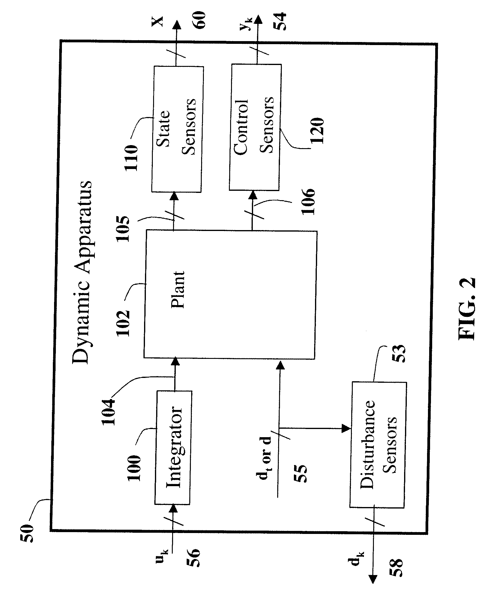
GENERAL ELECTRIC CO
View PDF12 Cites 21 Cited by
  • Summary
  • Abstract
  • Description
  • Claims
  • Application Information

AI Technical Summary

Benefits of technology

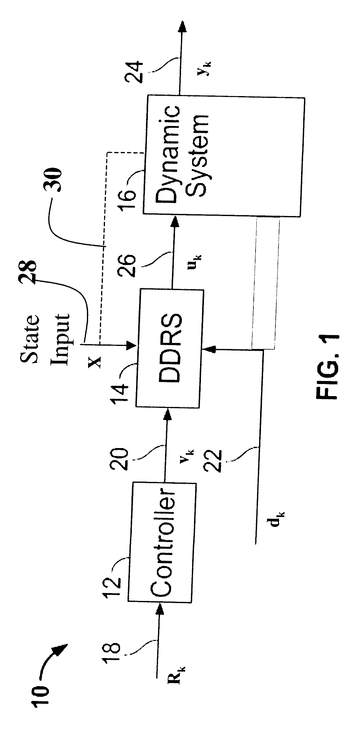
[0006]In one aspect, a method for reducing an effect of a disturbance signal on an output of a dynamic system is described.
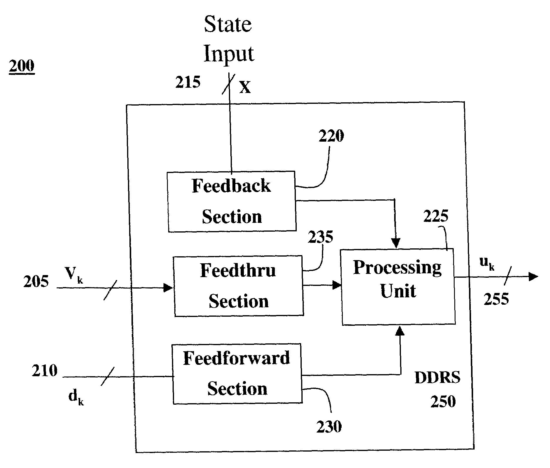
[0014]In accordance with one aspect a dynamic disturbance rejection device reduces an effect of a disturbance signal on an output of a controlled system. The device comprises at least one input command signal wherein the command signal effects one or more parameters of the controlled system. There is a feedback section with state information about the controlled system, wherein the feedback section generates a feedback gain output using inverse system dynamics. There is a feedforward section with disturbance information, wherein the feedforward section generates a feedforward output using inverse system dynamics. There is also a feedthru section coupled to the command signal, wherein the feedforward section generates a feedforward output using inverse system dynamics. A processing unit is coupled to the feedthru section, the feedback section and the feedforward section, wherein the processing unit processes a compensated control signal for the controlled system from the feedthru output, the feedback output and the feedforward output. The processing unit can be any form of processing capability and the coupling can be operatively coupled or otherwise allowing for the data transfer. The device according to one implementation comprises at least subtractors, adders, and multipliers.

Problems solved by technology

However, the dynamic system is subjected to a plurality of disturbances, which are inputs to the dynamic system that may have an undesirable effect on the output(s) of the system.

Method used


Image

  • System and methods for reducing an effect of a disturbance
  • System and methods for reducing an effect of a disturbance
  • System and methods for reducing an effect of a disturbance

Examples


Embodiment Construction

[0030]According to one embodiment, the system provides for reducing or eliminating the impact of disturbances to dynamic systems. More specifically, the systems and methods describe rejecting or attenuating the influence of measured or estimated system disturbances on system output(s).

[0031]There are many systems that incorporate some form of control theory across many industries, such as aerospace, marine, automotive, paper, plastics, food, and pharmaceutical, and across many disciplines such as mechanical, chemical, electrical, and magnetic. These controlled systems can have single or multiple control inputs as well as single or multiple regulated or controlled outputs. According to one embodiment, it is desired to regulate or control one or more of the system or process outputs by using one or more of the system control inputs. The signals used to regulate or control the process outputs of the dynamic system are called control inputs. Inputs other than the control inputs that may...


PUM


Abstract

A method and system for reducing disturbance effects on a dynamic system. The method in one embodiment processes a compensated control signal using at least one of a feedforward gain, feedthru gain and a feedback gain, and transmitting the compensated control signal to the dynamic system. An embodiment of the dynamic disturbance rejection device comprises a feedthru section with at least one input command signal that processes a feedthru output using inverse system dynamics, a feedback section with state information that processes a feedback output using inverse system dynamics, a feedforward section with disturbance information that processes a feedforward output using inverse system dynamics, and a processing unit that processes the compensated control signal for the controlled system.

Description

RELATED APPLICATIONS[0001]This application is a continuation-in-part of U.S. application Ser. No. 11 / 549,320, filed Oct. 13, 2006 and is herein incorporated in its entirety by reference.STATEMENT REGARDING FEDERALLY SPONSORED RESEARCH & DEVELOPMENT[0002]The invention described herein was made with Government support under Contract No. N00019-96-C-0176 awarded by the Department of Defense. The Government has certain rights to the invention.FIELD OF THE INVENTION[0003]The invention generally relates to control systems, and more particularly, to systems and methods for reducing the effects of disturbances for the system.BACKGROUND[0004]A dynamic system, such as a gas turbine, wind turbine, an engine, a motor, or a vehicle, has at least one input and provides at least one output based on the input(s). However, the dynamic system is subjected to a plurality of disturbances, which are inputs to the dynamic system that may have an undesirable effect on the output(s) of the system.[0005]Cur...

Claims


Application Information

Patent Timeline
Patent Type & Authority Applications(United States)
IPC IPC(8): G05B13/02
CPCG05B13/042G05B5/01
Inventor BRUNELL, BRENT JEROME
Owner GENERAL ELECTRIC CO
Learn More