
Noise resistant light-powered sensor

a light-powered sensor and noise-resistant technology, applied in the direction of optical radiation measurement, transmission monitoring, instruments, etc., can solve the problems of increasing the cost of the system, adding more weight, and the power requirements of conventional control systems can also be troublesome for designers

Active Publication Date: 2008-09-11
NORTHROP GRUMMAN SYST CORP
View PDF2 Cites 26 Cited by
  • Summary
  • Abstract
  • Description
  • Claims
  • Application Information

AI Technical Summary

Benefits of technology

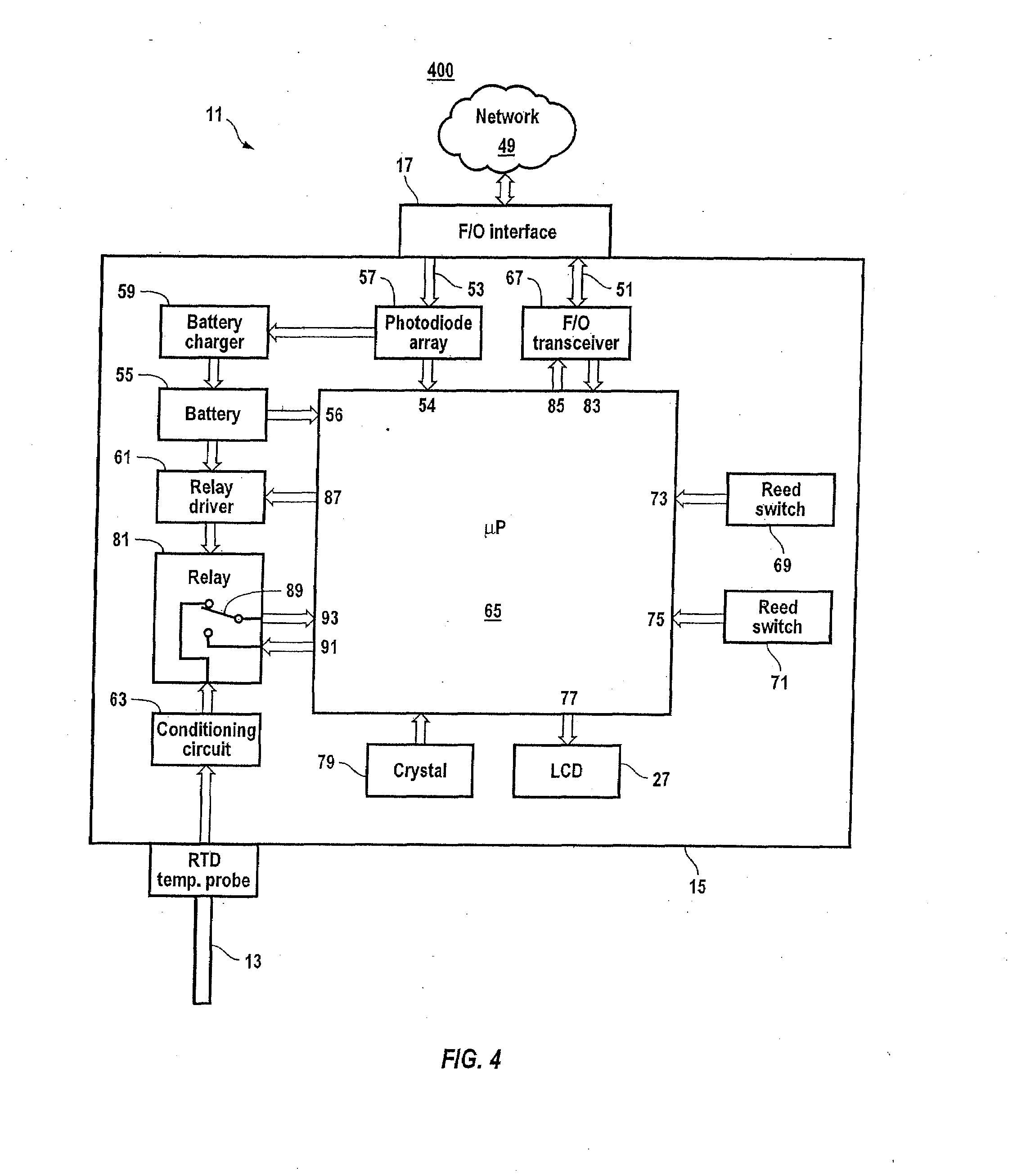
The present invention is a system that uses fiber optic technology to streamline process control and data acquisition. It includes smart sensors that communicate with a central computer or among themselves in a distributed network. The sensors have a microprocessor, fiber optic transceiver, signal conditioning circuit, and photovoltaic power converter enclosed in a Faraday cage to make them immune to electromagnetic interference. The sensors measure process parameters such as temperature, pressure, or flow and convert them to digital signals using a microprocessor. The high intensity light transmitted along optical fibers provides a clean source of power for sensor communications. The system also includes a fiber optic splitter that provides power to the sensors and communicates with them through optical fibers. The splitter can be connected in a centralized or distributed architecture, and verification algorithms can be run automatically through commands from a central computer or other processors within the network. The system is designed to be efficient, reliable, and immune to interference.

Problems solved by technology

Conventional control systems pose a number of challenges for designers in applications where system components must operate with high reliability.
These schemes add to the cost of the system, and in aircraft applications undesirably add more weight.
The power requirements of conventional control systems can also be troublesome to designers.
The potential exposure of the power lines to damage or interference further complicates system integrity.
Battery-operated sensors can be used to reduce cabling, but the tradeoff burdens operators with periodic battery replacement and battery charger maintenance.
In aircraft, the control circuits are inherently noisy, especially those operating at 400 Hz.
Despite judicious use of these features, the systems remain susceptible to noise-induced interference.
This places another substantial burden on plant operations.

Method used


Image

  • Noise resistant light-powered sensor
  • Noise resistant light-powered sensor
  • Noise resistant light-powered sensor

Examples


Embodiment Construction

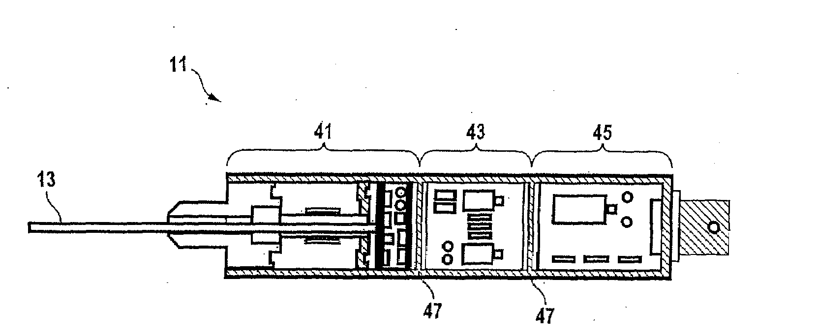
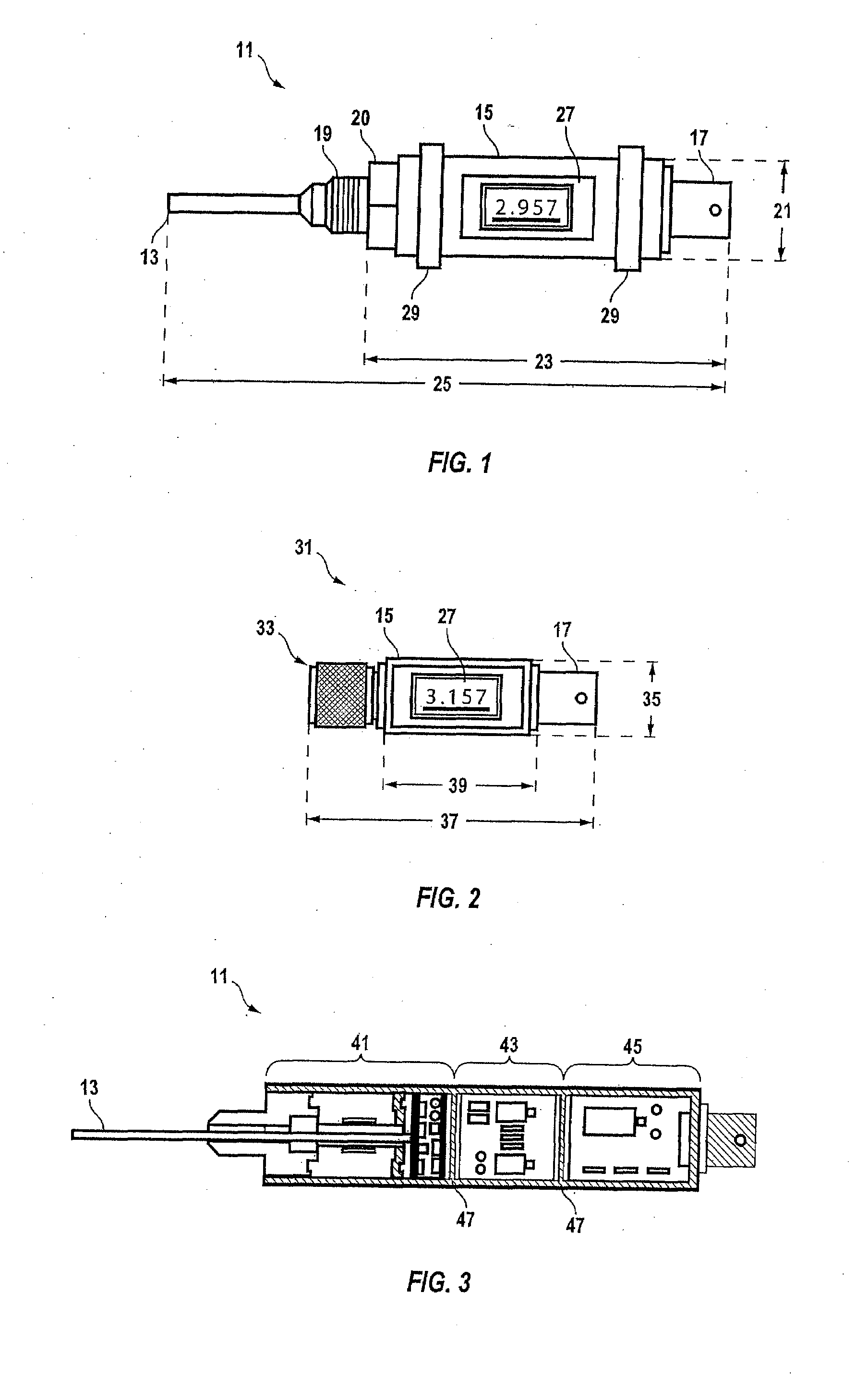
[0026]The present invention describes a network architecture for a distributed control system of light-powered sensors, light-powered control receivers, and light-powered on-off status monitors. These unique devices, when connected via fiber optic transmission lines comprise an advanced, integrated sensor and control network. The light-powered sensors, or smart sensors, may interface electrically and mechanically as a distributed system, or as a centralized system that can be configured to perform any process control function regardless of size and complexity. The smart sensor accurately and reliably reads an analog signal from a transducer then transmits the result in digital serial format to the central computer over a dedicated full duplex fiber optic line qualified to operate in extremely severe electromagnetic or tactical military environments.

[0027]The smart sensor continuously reads the analog transducer and upon receiving a request from elsewhere in the network, instantly re...


PUM


Abstract

A light-powered data acquisition and control system immune to electromagnetic interference employs smart sensors in a network configuration capable of decentralized communication. A smart sensor with integral transducer encloses a microprocessor, fiber optic transceiver, and photovoltaic converter within a Faraday cage. Optical fibers link plural sensors for duplex communication with a fiber optic splitter, which transmits high intensity light to the converter for powering the sensors. The sensor converts analog input from the transducer into bit packets for fiber optic transmission to the network via the splitter. Firmware in the splitter converts the bit packets to network protocol and vice versa enabling data communication among sensors, splitters, and control receivers. Verification algorithms for testing sensors are run automatically by the microprocessor or through commands issued via the network. Mnemonics stored in the sensors provide automatic updating of system configuration.

Description

CROSS-REFERENCE TO RELATED APPLICATIONS[0001]This application is a divisional of application Ser. No. 11 / 409,627 filed Apr. 24, 2006 for Smart Integrated Distributed Light-Powered Process Systems and is related to divisional application Serial Number ______ filed ______ for a Noise Resistant Light-Powered Transceiving Adapter.[0002]The U.S. Government has a paid-up license in this invention and the right in limited circumstances to require the patent owner to license others on reasonable terms as provided for by the terms of Contract No. DASG60-096-C-01555 awarded by the U.S. Army Cruise Missile Defense Command.BACKGROUND OF THE INVENTION[0003]1. Field of the Invention[0004]The present invention relates to process control and data acquisition systems. More specifically, the invention relates to integrated, fiber optically powered data acquisition, control and data transmission systems.[0005]2. Description of Related Art[0006]Computerized control systems and data acquisition systems ...

Claims


Application Information

Patent Timeline
Patent Type & Authority Applications(United States)
IPC IPC(8): G01M19/00G01M99/00
CPCG01D5/268G01D5/2515
Inventor NYFFENEGGER, JOHANNES F.REDMER, ROBERT E.
Owner NORTHROP GRUMMAN SYST CORP
Learn More