Dryer

a technology of drying rack and drying rack, which is applied in the field of drying rack to achieve the effect of reducing the time required to dry the user's hands evenly and quickly, and minimising the risk of small areas of the user's hands

Active Publication Date: 2008-09-18
DYSON TECH LTD
View PDF100 Cites 37 Cited by
  • Summary
  • Abstract
  • Description
  • Claims
  • Application Information

AI Technical Summary

Benefits of technology

[0007]Both aspects of the invention provide arrangements in which, in use, the distance between the openings through which drying air is emitted and the adjacent surfaces of the user's hands is kept substantially constant. This is particularly advantageous when the undersides (or palms) of the users hands are considered.
[0008]Preferably, the front edge of the cavity entrance is substantially straight and the rear edge is curved. More preferably, the rear edge comprises two curved portions which are arranged symmetrically about the centre of

Problems solved by technology

This will result in the user needing to use the dryer to dry part of his or her hands after

Method used


Image

  • Dryer
  • Dryer
  • Dryer

Examples


Embodiment Construction

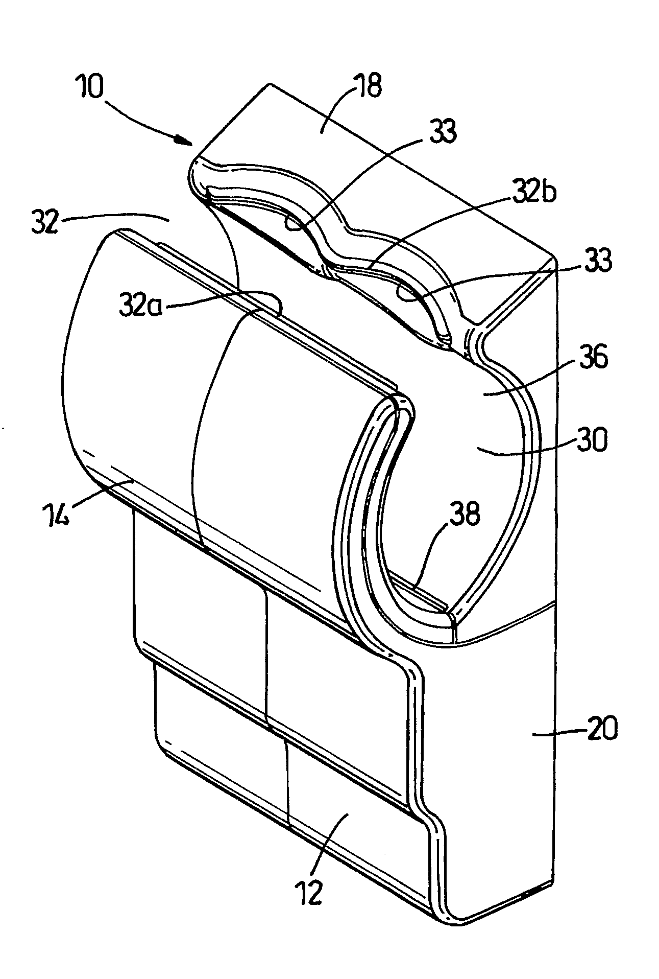
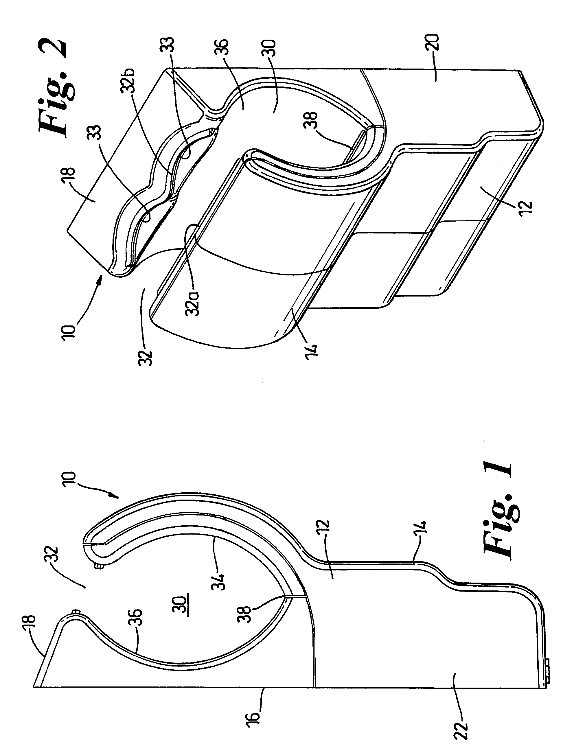
[0018]Referring firstly to FIGS. 1 and 2, the hand dryer 10 shown in the drawings comprises an outer casing 12 having a front wall 14, a rear wall 16, an upper face 18 and side walls 20, 22. The rear wall 16 can incorporate fixing devices (not shown) for securing the hand dryer 10 to a wall or other structure prior to use. An electrical connection (not shown) is also provided on the rear wall or elsewhere on the casing 12. A cavity 30 is formed in the upper part of the casing 12 as can be seen from FIGS. 1 and 2. The cavity 30 is open at its upper end and delimited thereat by the top of the front wall 14 and the front of the upper face 18. The space between the top of the front wall 14 and the front of the upper face 18 forms a cavity entrance 32 which is sufficiently wide to allow a user's hands to be introduced to the cavity 30 through the cavity entrance 32. The cavity 30 is also open to the sides of the hand dryer 10 by appropriate shaping of the side walls 20, 22.

[0019]The cavi...


PUM


Abstract

A hand drying apparatus has a casing, a cavity formed in the casing for receiving a user's hands, a fan located in the casing and creating an airflow, and a plurality of openings communication with the fan and arranged to direct an airflow transversely across the cavity. The cavity has an entrance delimited by a front edge and a rear edge in which the openings are located. The shape of the front and rear edges is such that, when in use the user's hands are introduced to the cavity, the distance between the user's hands and the nearest opening is substantially uniform. Alternatively, one of the edges is substantially straight and the other of the said edges is curved so that the distance between the edges varies along the length of the cavity entrance. These arrangements enhance the drying efficiency of the dryer.

Description

REFERENCE TO RELATED APPLICATIONS[0001]This application is a national stage application under 35 USC 371 of International Application No. PCT / GB2006 / 002139, filed Jun. 13, 2006, which claims the priority of United Kingdom Application No. 0515752.4, filed Jul. 30, 2005, the contents of which prior applications are incorporated herein by reference.FIELD OF THE INVENTION[0002]The invention relates to a dryer which makes use of narrow streams of high velocity, high pressure air to dry a user's hands.BACKGROUND OF THE INVENTION[0003]The use of air jets to dry hands is well known. Examples of hand dryers which emit at least one air jet for the purposes of drying hands are shown in GB 2249026A, JP 2002 034835A and JP 2002306370A. A further example of a known hand dryer is shown in JP 11244191. In this latter prior art document, the cavity into which the user is invited to place his or her hands is shaped by providing the cavity with curved walls. Nozzles are provided in the curved walls so...

Claims


Application Information

Patent Timeline
IPC IPC(8): A47K10/48
CPCA47K10/48B05B1/044F26B19/00A47K2210/00
Inventor CHURCHILL, JOHNDYSON, JAMESGAMMACK, PETER DAVID
Owner DYSON TECH LTD
Why Eureka
Try Eureka