Device and method for a fiber evaporation engine

Inactive Publication Date: 2008-09-18
WIESNER STEPHEN J
View PDF6 Cites 5 Cited by
  • Summary
  • Abstract
  • Description
  • Claims
  • Application Information

AI Technical Summary

Benefits of technology

[0015]It is a further object of the present invention to provide an evaporation engine capable of producing a practical amount of recoverable energy.
[0016]An evaporation engine system is disclosed for producing usable energy by application of alternate cycles of a cold liquid and available hot dry air. The system includes a vessel containing the cold liquid, a wheel partially submerged in the cold liquid, wherein the wheel is mounted on a first bearing on the crankshaft located at the axis of the wheel. The system also includes a second bearing on the crankshaft parallel to and fixed horizont

Problems solved by technology

The world is running out of oil.
Society is more and more dependent on the last big pools of oil, with consequences that are problematic for the U.S. and most of the rest o

Method used


Image

  • Device and method for a fiber evaporation engine
  • Device and method for a fiber evaporation engine
  • Device and method for a fiber evaporation engine

Examples


Embodiment Construction

[0025]The principles and operation of a method and an apparatus according to the present invention may be better understood with reference to the drawings and the accompanying description, it being understood that these drawings are given for illustrative purposes only and are not meant to be limiting.

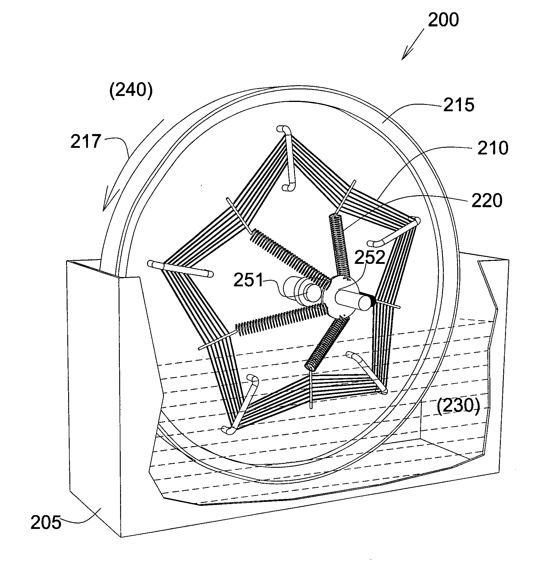
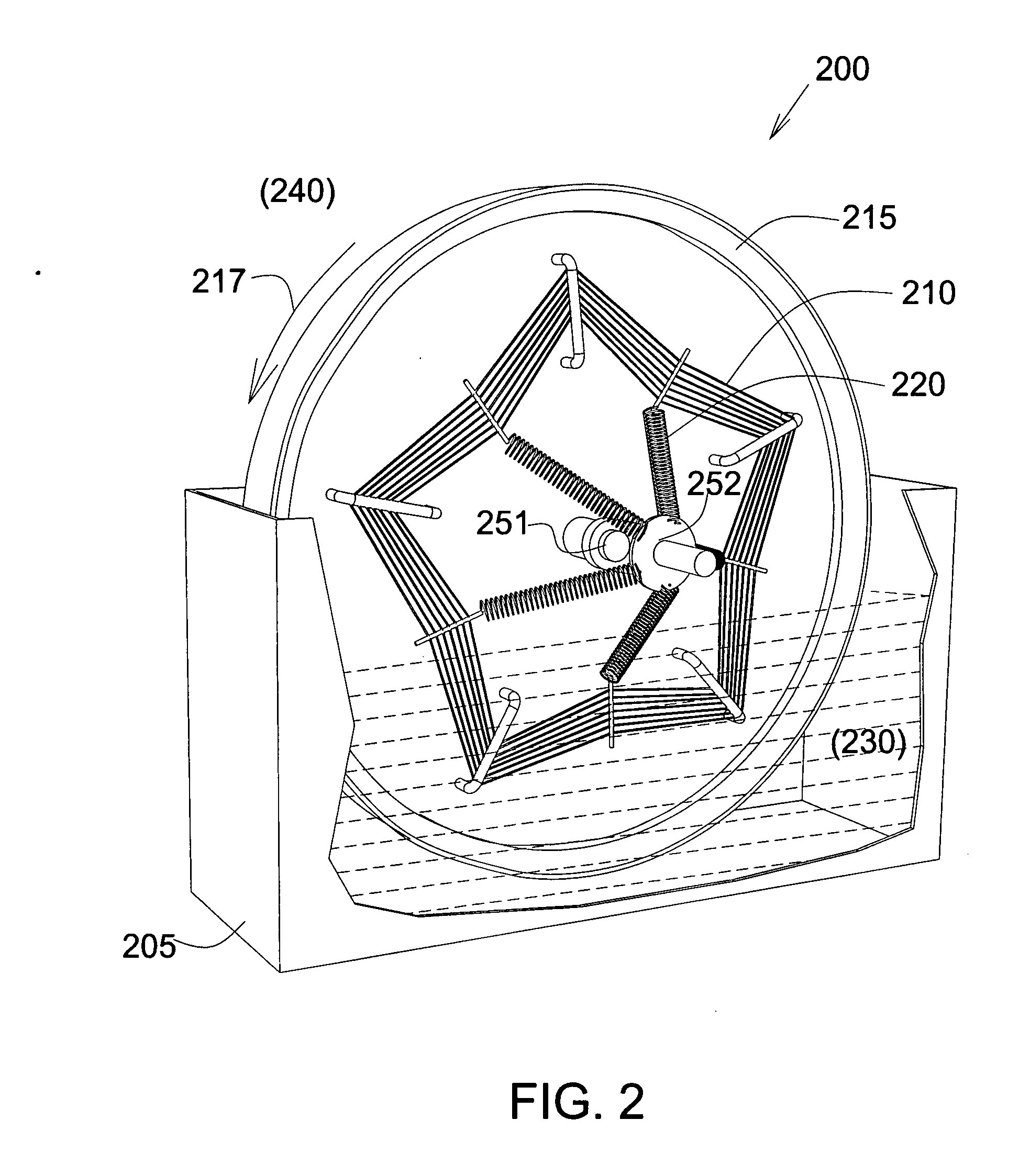
[0026]Reference is now made to FIG. 2, a schematic illustration of a side view of an improved evaporation engine design, constructed in accordance with the principles of the present invention.

[0027]The active elements of the engine 200 are cords 210, which shrink when they are wet and recover their length when they are dry. Cords 210 act like the pistons on a car. They are connected through springs 220 to a crankshaft. However, on this engine, the crankshaft is stationary and cords 210 are on a wheel 215, which rotates around the crankshaft. The crankshaft has a first bearing 251 at the axis of the wheel and a second bearing 252 on crankshaft 252 is parallel to and fixed horizontally r...


PUM


Abstract

An evaporation engine system for producing usable energy by application of alternate cycles of a cold liquid and available hot dry air. The system includes a vessel containing the cold liquid, a wheel partially submerged in the cold liquid, wherein the wheel is mounted on a first bearing on the crankshaft located at the axis of the wheel. The system also includes a second bearing on the crankshaft parallel to and fixed horizontally relative to the first bearing and a plurality of cords connected between the rim of the wheel and the second bearing, such that with each rotation of the wheel the plurality of cords dip into the cold liquid at the bottom of the rotation, wherein the plurality of cords shrink causing the plurality of cords come out again into the warm, dry air at the top of the rotation, wherein the plurality of cords become dry and as a result of the drying the plurality of cords lengthen, such that the rotation of the wheel becomes self-sustaining, wherein the rotation is available as an energy source.

Description

FIELD OF THE INVENTION[0001]The present invention relates to a system and a method for an evaporation engine. More specifically, the present invention relates to an improved device and method for an evaporation engine using fiber and springs, for use as a primary source of power.BACKGROUND OF THE INVENTION[0002]The world is running out of oil. Society is more and more dependent on the last big pools of oil, with consequences that are problematic for the U.S. and most of the rest of humanity. Every potential source of energy should be considered. Some sources have received extensive investigation, such as wind power, nuclear, hydro and solar.[0003]Evaporation engines could supply vast amounts of power. Reference is made to an article by Zaslavsky on Philip Carlson's “Power Tower,” which is basically an as yet unfulfilled proposal for a multi-billion dollar development on a large scale, as shown in prior art FIG. 1. The article is entitled “Solar Energy Without a Collector for Electri...

Claims


Application Information

Patent Timeline
IPC IPC(8): F03G7/06
CPCF03G7/06
Inventor WIESNER, STEPHEN J.
Owner WIESNER STEPHEN J
Why Eureka
Try Eureka