Self Adjusting Lock System And Method

a self-adjusting and lock technology, applied in the direction of cylinder locks, electric permutation locks, register/indication, etc., can solve the problems of failure of electrical lock operation and cost savings

Inactive Publication Date: 2008-09-18
AMIR HAIM
View PDF15 Cites 40 Cited by
  • Summary
  • Abstract
  • Description
  • Claims
  • Application Information

AI Technical Summary

Benefits of technology

[0014]Preferably, the control and rotational unit is adapted to mathematically operate upon the initial and the at least one subsequent current-versus-time profile to create and store a comparative current-versus-time profile. Most preferably, the control and rotational unit is further adapted to calculate and store an electrical current threshold value and a time interval threshold value for respective events of the comparative current-versus-time profile based on data from corresponding respective events of the initial and subsequent current-versus-time profiles. Typically, the electrical current threshold and time interval threshold values represent respective upper limit values corresponding to respective events. Most typically, the control and rotation unit is further adapted to compare sensed motor current and measured times of motor operation against the stored comparative current-versus-time profile and to determine whether instant sensed current and measured times do not exceed values of the comparative current-versus-time profile.
[0015]Preferably, the control and rotation unit is adapted to set a warning flag when at least one of the instant sensed current and measured times exceed values of the comparative current-versus-time profile. Most preferably, the control and rotation unit is further adapted to compare sensed motor current and measured times of motor operation against the stored respective threshold values and to set an error flag when at least one respective threshold value is exceeded.
[0016]Preferably, the control and rotation unit is further adapted to self adjust the lock system when at least one threshold value is exceeded, the self-adjustment being at least one chosen from the list including: stopping motor operation; reversing motor operation; and recording the sensed motor current and time values. Most preferably, the control and rotation unit is adapted to command rotation of the motor for a predetermined time to determine whether sensed current values are excessive and to stop motor operation for lock system servicing if sensed current values be excessive. Typically, the control and rotat

Problems solved by technology

However, in an electrically operated lock (especially one having a motor with limited torque or having a limited power source, such as a battery-powered motor) degradation in lock operation due to any of the causes noted hereinabove could

Method used


Image

  • Self Adjusting Lock System And Method
  • Self Adjusting Lock System And Method
  • Self Adjusting Lock System And Method

Examples


Embodiment Construction

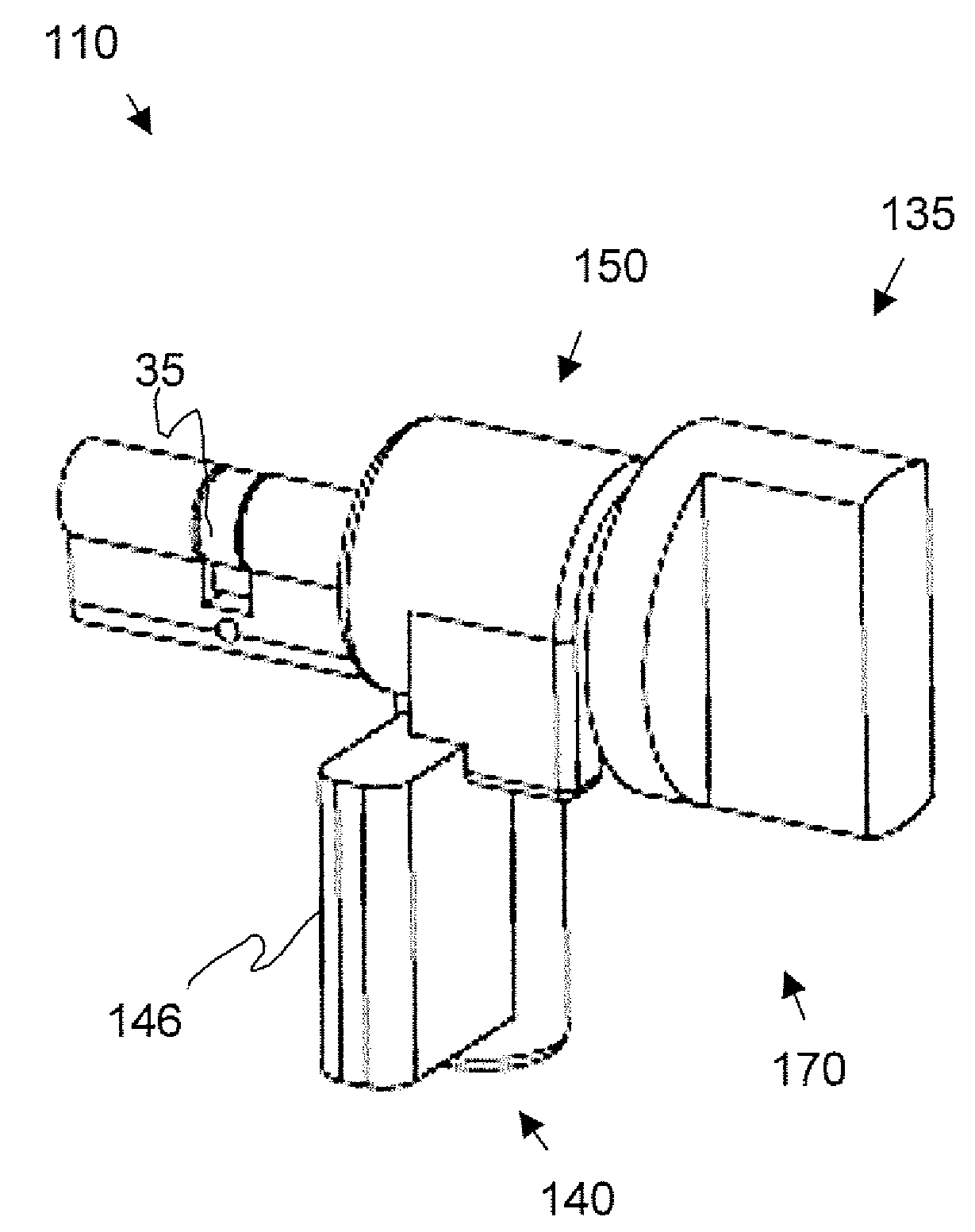
[0026]The present invention includes a lock apparatus that can be operated to bolt and unbolt a lock, such as used in doors, and one which may also be operated mechanically in case of power failure.

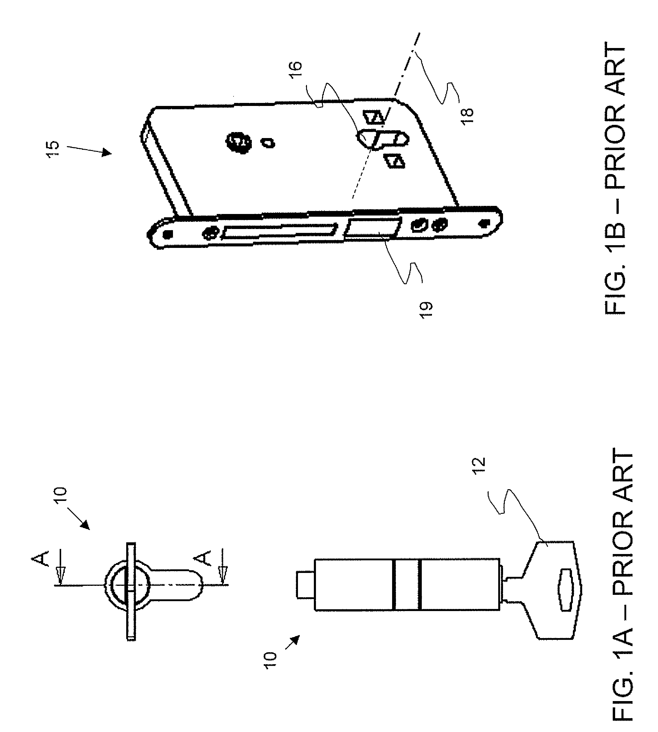
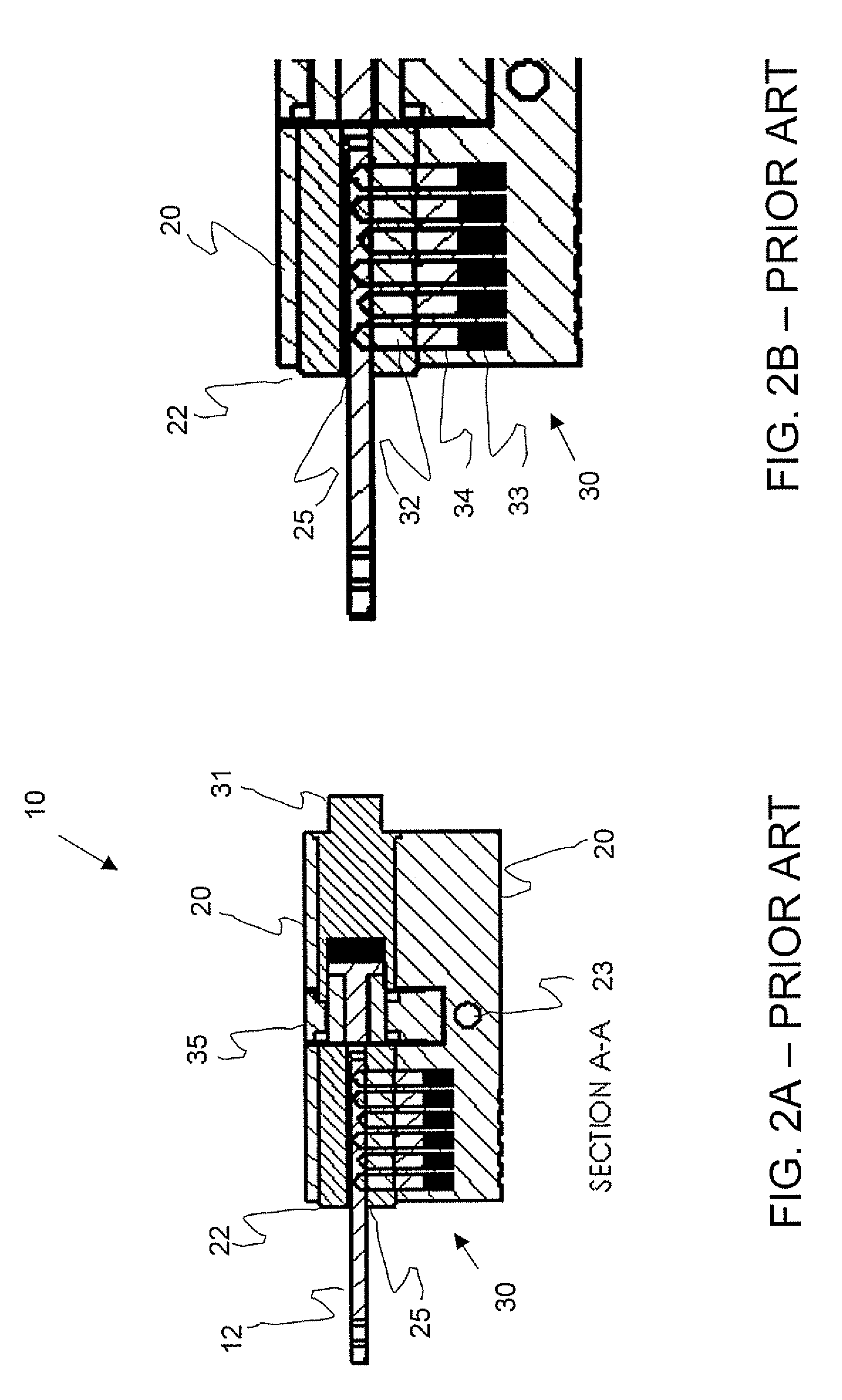
[0027]Reference is now made to FIGS. 3A and 3B, which are, respectively, an illustrative diagram and a sectional diagram of a self-adjusting lock system 110 in accordance with an embodiment of the present invention. Apart from differences described below, self-adjusting lock system 110 is generally similar to operation of cylinder lock 10 as shown in FIGS. 2A and 2B, so that elements indicated by the same reference numerals are generally identical in configuration and operation. Embodiments of the current invention disclosed hereinbelow are directed to be generally replaceable to cylinder lock 10 and / or retrofittable to cylinder lock 10 in door lock 15 shown in FIGS. 1A, 1B, 2A, and 2B. Specifically, self-adjusting lock system 110 has a “blind cylinder”, in that a key can be inserted into...


PUM


Abstract

A self adjusting lock system including: a lock cylinder having a direction of elongation defining an axial direction for the system and having a first and a second end; a rotatable first cylindrical plug in the lock cylinder, the first plug having an axially extending key slot from the first end of the lock cylinder; a rotatable second cylindrical plug in the lock cylinder, the second plug substantially coaxial to the first cylindrical plug; a bolt which is retractable substantially perpendicularly to the axial direction by rotation of each of the first plug and the second plug; and a control and rotation unit adapted to rotate the second plug, including: a power source, a processor; a motor; a current sensor adapted to sense motor current; and a clock adapted to measure time; wherein the control and rotation unit is adapted to sense motor current over time and to adjust operation of the lock system dependent on the sensed motor current over time.

Description

FIELD AND BACKGROUND OF THE INVENTION[0001]The present invention relates to a self adjusting lock system and, in particular, it concerns a self adjusting retrofittable system that can be operated to bolt and unbolt a lock, such as used in doors, and one which may also be operated mechanically in case of power failure.[0002]In a conventional mechanical cylinder lock, when an appropriate matching key is inserted into the cylinder lock, the key serves to mechanically align tumbler pins (“unlocked” or “opened” state), allowing the cylindrical plug to be rotated freely to retract a bolt which is typically mechanically connected the cylindrical plug and is driven by the rotated cylindrical plug. Retraction of the bolt is typically referred to as “unbolting” the lock. Conversely, when the cylindrical plug is rotated (usually in a direction opposite that used for unbolting) and the bolt is extended in such a way as to inhibit movement of a door or window, etc. the action is referred to as “...

Claims


Application Information

Patent Timeline
IPC IPC(8): E05B49/02
CPCE05B47/00E05B47/0012E05B2047/0094E05B2047/002E05B2047/0067E05B63/0017Y10T70/7638Y10T70/8081Y10T70/7136
Inventor AMIR, HAIM
Owner AMIR HAIM
Why Eureka
Try Eureka