Component With Compressive Residual Stresses, Process For Producing And Apparatus For Generating Compressive Residual Stresses

a technology of compressive residual stress and compressive residual stress, which is applied in the direction of efficient propulsion technology, manufacturing tools, machines/engines, etc., can solve the problem that the compressive residual stress according to the prior art is not strong enough for unusual operating states

Active Publication Date: 2008-09-18
SIEMENS ENERGY GLOBAL GMBH & CO KG
View PDF17 Cites 29 Cited by
  • Summary
  • Abstract
  • Description
  • Claims
  • Application Information

AI Technical Summary

Problems solved by technology

Components according to the prior art do not have sufficient strength for unusual operatin...

Method used


Image

  • Component With Compressive Residual Stresses, Process For Producing And Apparatus For Generating Compressive Residual Stresses
  • Component With Compressive Residual Stresses, Process For Producing And Apparatus For Generating Compressive Residual Stresses
  • Component With Compressive Residual Stresses, Process For Producing And Apparatus For Generating Compressive Residual Stresses

Examples


Embodiment Construction

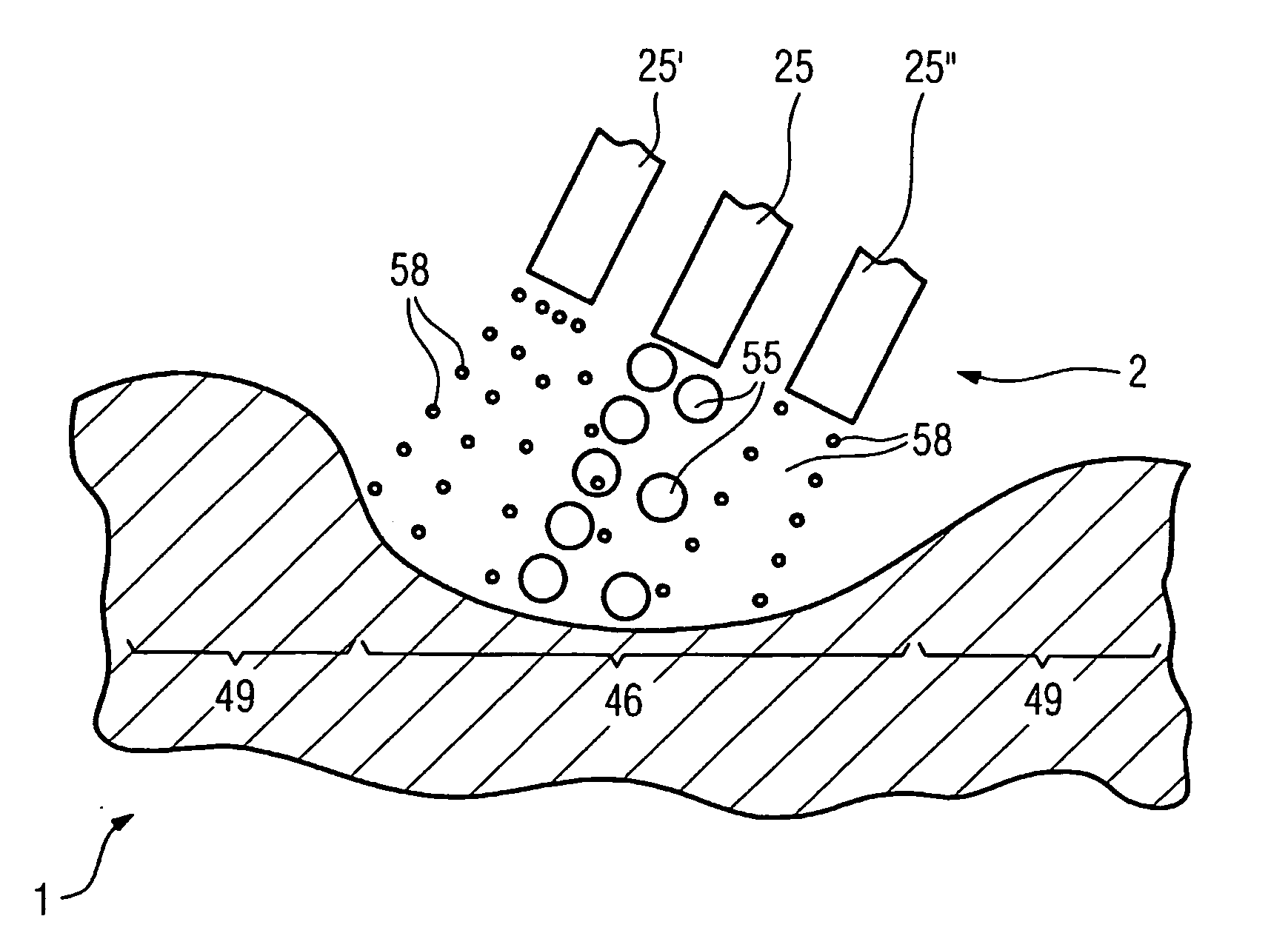
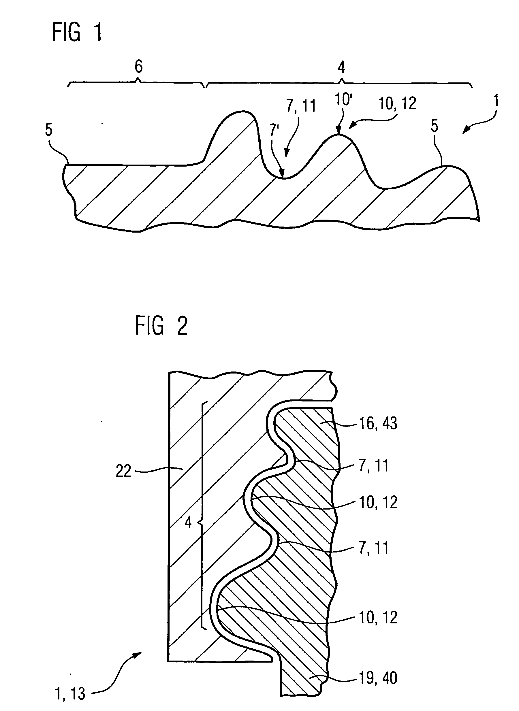
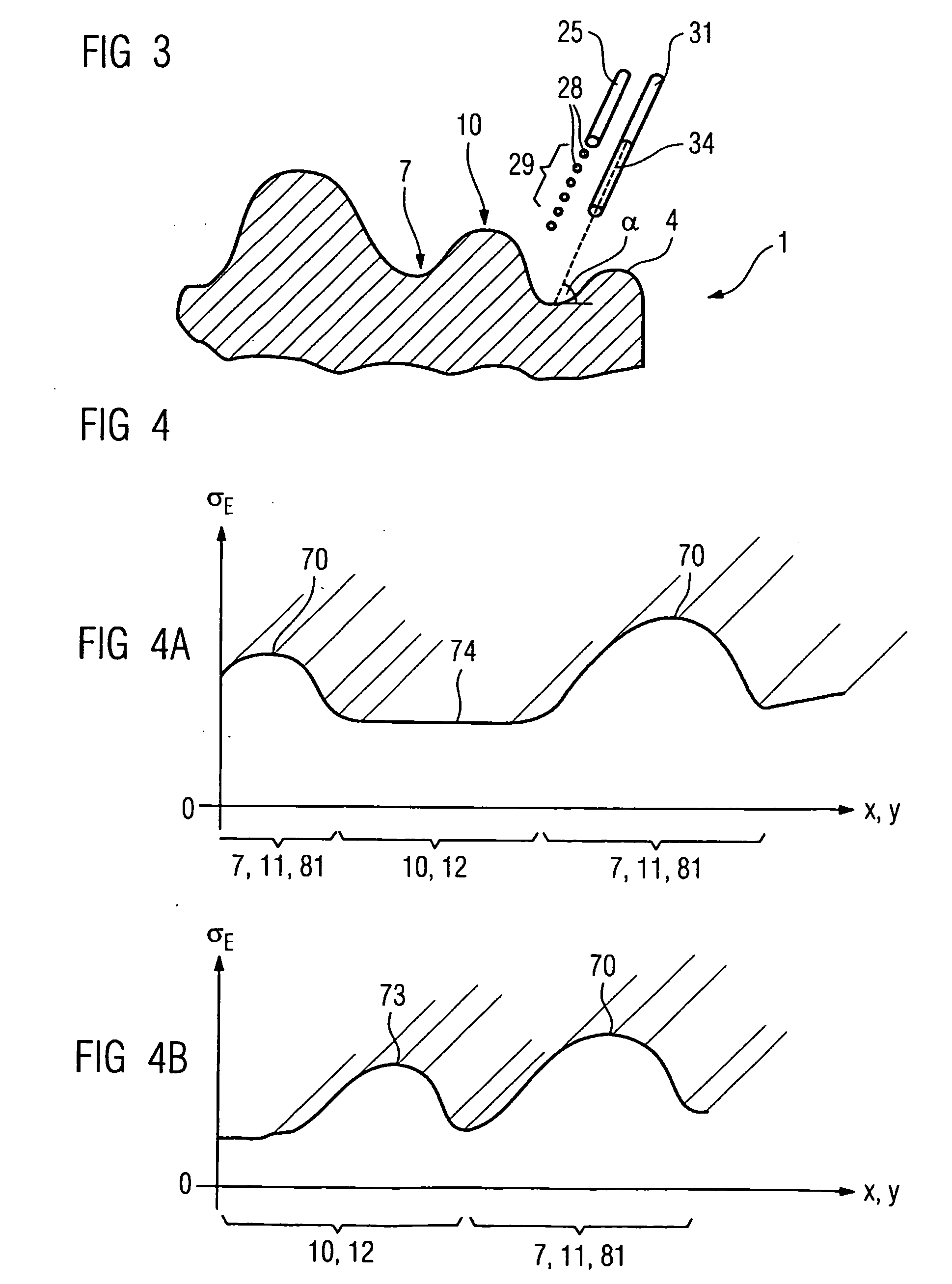
[0023]FIG. 1 shows a component 1 having a surface 5. The component 1 may be a component of a steam turbine (FIG. 17) or of a gas turbine, such as for example an aircraft turbine or a turbine for generating electricity 100 (FIG. 16). Components of this type are, for example, turbine blades or vanes 120, 130, 342, 354, a combustion chamber lining or other housing parts.

[0024]The surface 5 of the component 1, 120, 130, 342, 354 is composed, for example, of a plurality of, in this case two, surface regions 4, 6. A surface region 6 (for example main blade or vane region 40, FIG. 15) is, for example, planar or has just a single curvature, whereas the surface region 4 is multiply curved. Different compressive residual stresses σE that are different than zero are present in the surface 5 and its surface regions 4 and / or 6.

[0025]The component 1, 120, 130, 342, 354 has a concavely curved region 7 of the surface region 4, which for example while the component 1, 120, 130, 342, 354 is in use is...


PUM

PropertyMeasurementUnit
Fractionaaaaaaaaaa
Fractionaaaaaaaaaa
Fractionaaaaaaaaaa

Abstract

The inventive method discloses the local, adapted and controlled introduction of internal compressive stress in convex and concave regions, such as the root region of turbine blades, by means of at least two pressure generators.

Description

CROSS REFERENCE TO RELATED APPLICATIONS[0001]This application is the US National Stage of International Application No. PCT / EP2004 / 014300, filed Jan. 15, 2004 and claims the benefit thereof. The International Application claims the benefits of European Patent application No. 04000775.9 filed Jan. 15, 2004. All of the applications are incorporated by reference herein in their entirety.FIELD OF THE INVENTION[0002]The invention relates to a component having compressive residual stresses in accordance with the claims and to a process for producing a component having compressive residual stresses as described in the claims and to an apparatus for generating compressive residual stresses as described in the claims.BACKGROUND OF THE INVENTION[0003]Compressive residual stresses are often introduced into components which are subject to high mechanical loads, to enable the components to withstand increased stresses. This is in some cases carried out in the case of fir-tree-like roots of blade...

Claims


Application Information

Patent Timeline
IPC IPC(8): C21D7/06F01D5/28B24C1/10C21D7/04C21D7/08C21D10/00F01D5/30
CPCB24C1/10C21D7/06F01D5/286F01D5/3007Y10T29/479F01D5/3038F01D5/3046Y02T50/67F01D5/3023Y02T50/60
Inventor DAVID, WALTER
Owner SIEMENS ENERGY GLOBAL GMBH & CO KG
Why Eureka
Try Eureka