Electromagnetic rotation and stability apparatus

a technology of rotation and stability, applied in the direction of force measurement, material strength using tensile/compressive forces, instruments, etc., can solve the problems of limiting the usefulness of such product testing to approximate real field data, limiting the force being applied to an object, and impossible, etc., to achieve the effect of sufficient strength

Inactive Publication Date: 2008-09-18
BRIDGESTONE FIRESTONE NORTH AMERICAN TIRE
View PDF53 Cites 23 Cited by
  • Summary
  • Abstract
  • Description
  • Claims
  • Application Information

AI Technical Summary

Problems solved by technology

Unfortunately, in most cases, the evaluation of a specimen's characteristics of a particular property must be completed in isolation from other forces.
This limits the usefulness of such product testing to approximate real field data for the reason that in most field applications of an elastomeric product it is difficult, if not impossible, to limit the forces being applied to an object to just one force which is applied in only one direction.

Method used


Image

  • Electromagnetic rotation and stability apparatus
  • Electromagnetic rotation and stability apparatus
  • Electromagnetic rotation and stability apparatus

Examples


third embodiment

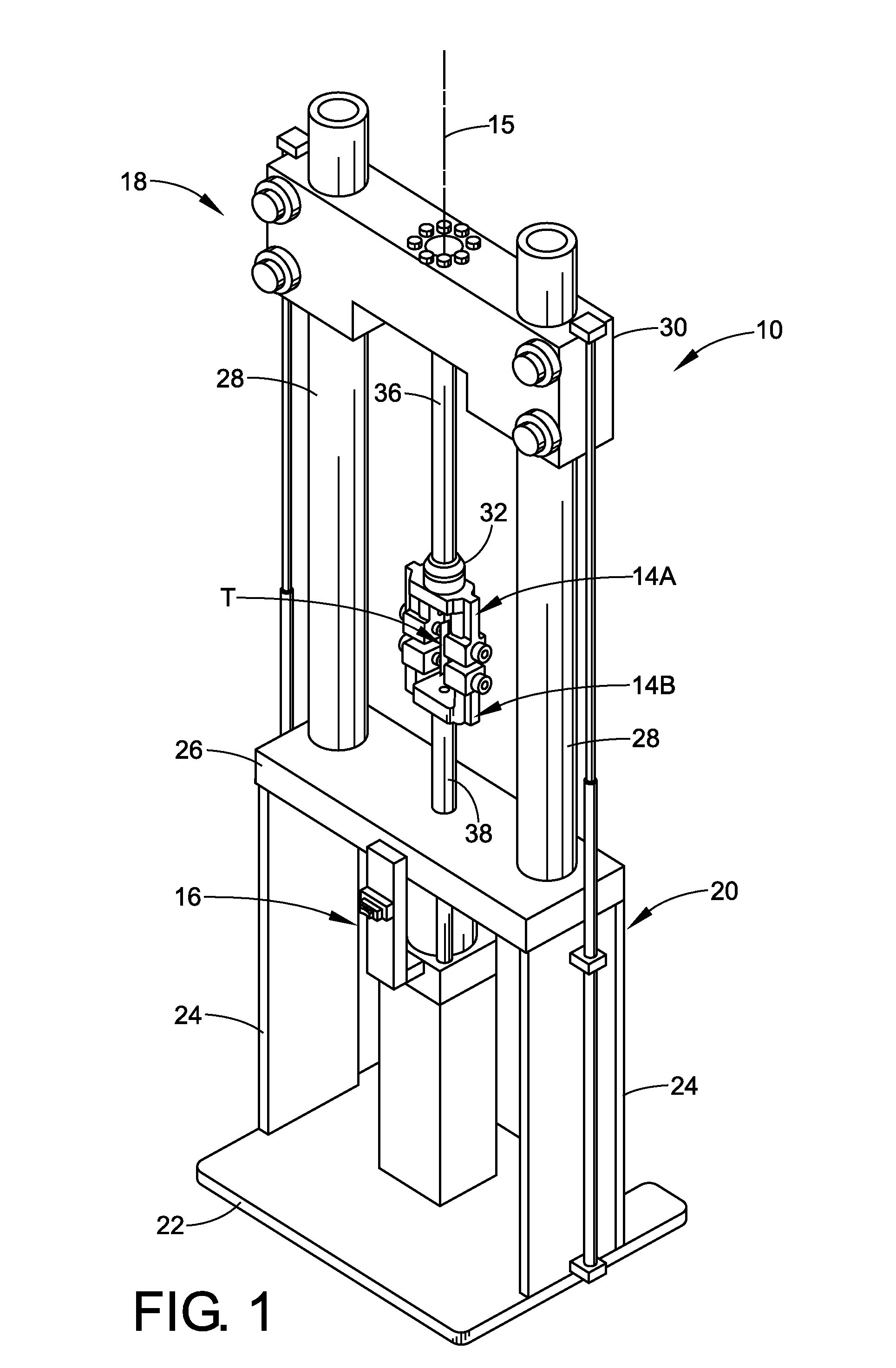
[0027]With reference to FIG. 5, the invention is illustrated. In this embodiment, an electromagnetic motor is incorporated into the testing machine. In this embodiment, support 38 extends from actuator 16, through crossbeam 26 to fixture 14B in a manner that will allow support 38 to rotate. Electromagnetic motor 52 is located near one end of support 38. The motor includes a plurality of electromagnets 54. Upon the application of an electrical current to motor 52, magnets 54 produce a magnetic field in the direction of arrow A of sufficient strength to cause support 38 to rotate and thereby rotate fixture 14B.

fourth embodiment

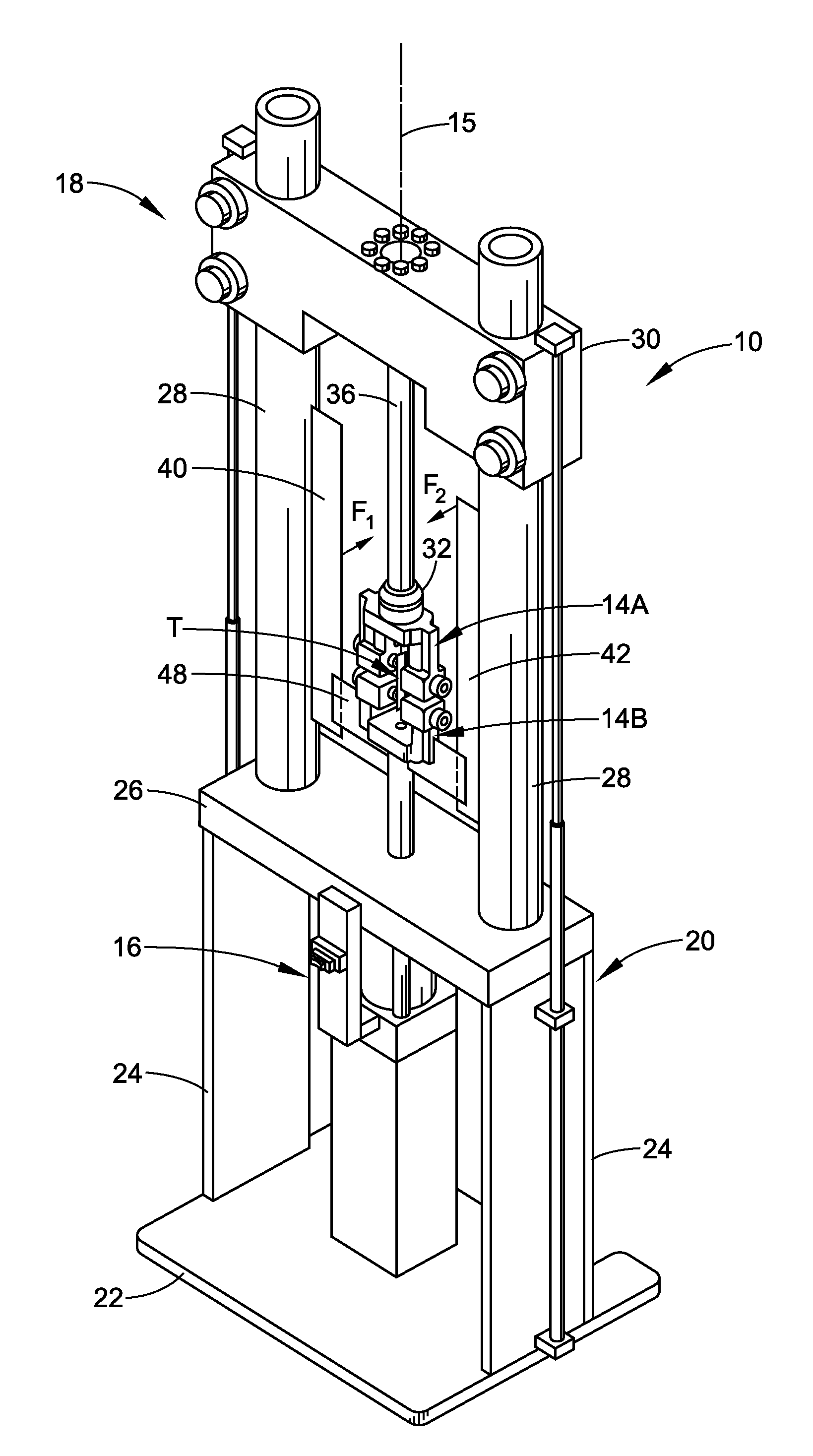
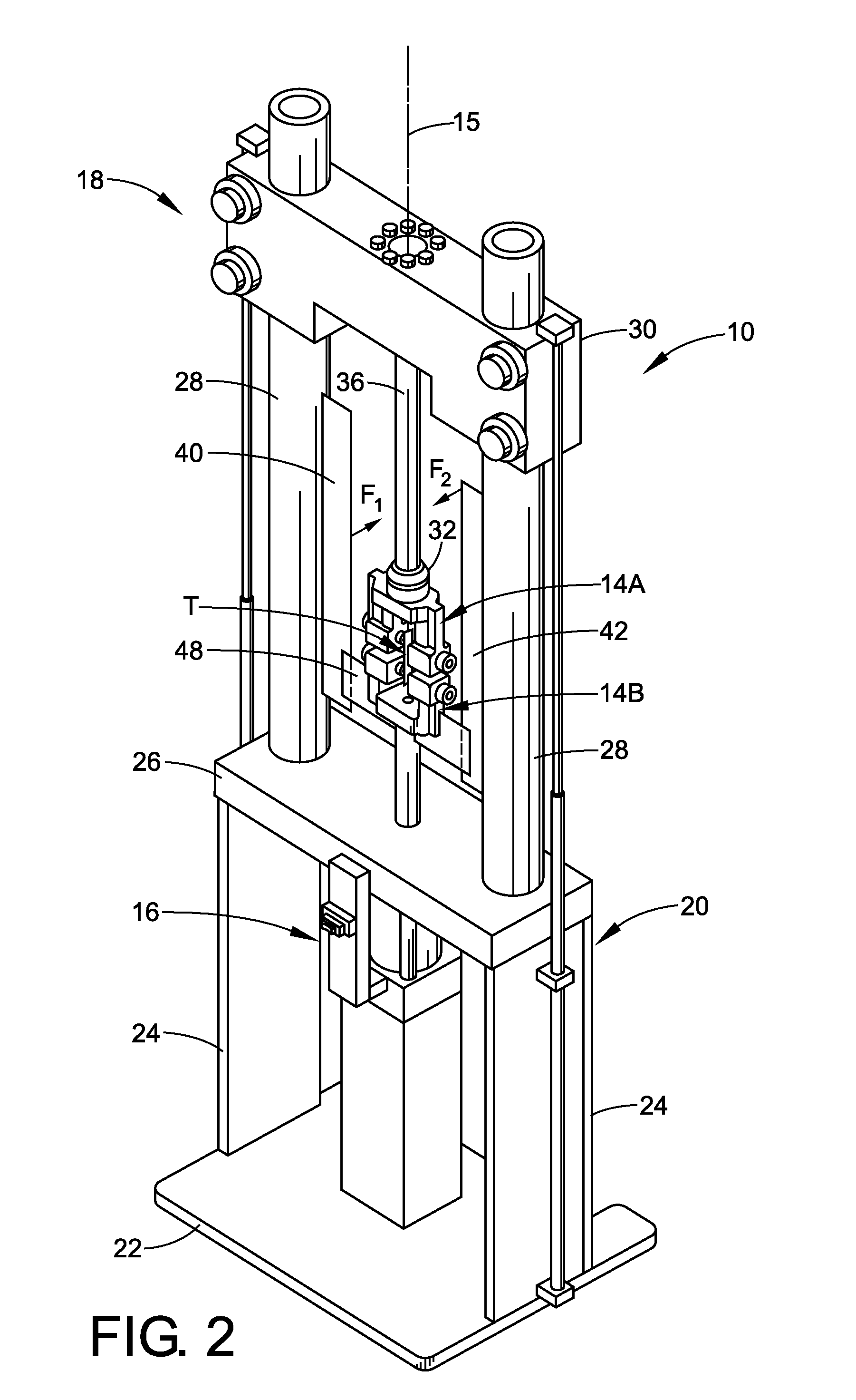
[0028]FIG. 6 illustrates the invention. In this embodiment, magnet 56 is attached to support columns 28 and is oriented diagonally between support columns 28. Magnet 56 can be either a permanent magnet or an electromagnet. Structure 48 is attached to test fixture 14B. Structure 48 is made of a material capable of reacting to the magnetic force exerted by magnet 56. As fixture 14B is moved along axis 15, the magnetic force is exerted onto structure 48 at localized points, i.e. the place on structure 48 that is the closest to magnet. Thus, as fixture 14B is moved along axis 15, the localized magnetic force exerted on structure 48 moves along structure 48 in a perpendicular relationship to axis 15. This causes fixture 14B to rotate as it is moved along axis 15, which in turn causes the test specimen to rotate. Angle α may be modified to change the rate of rotation relative to the amount of displacement of fixture 14B. A smaller angle α will create a very low rate of rotation relative t...


PUM

PropertyMeasurementUnit
angleaaaaaaaaaa
forceaaaaaaaaaa
magnetic forceaaaaaaaaaa

Abstract

A test machine for testing the physical properties of a test specimen is provided. The test machine includes a fixture that applies a first force on the test specimen in a first direction and utilizes magnetic force to bring about the rotation of a fixture to apply a second force on the test specimen in a second direction. The test machine can better simulate field applications where a material may experience, for example compression or tension at the same time it experiences a rotational moment.

Description

BACKGROUND[0001]The present exemplary embodiment relates to a material testing apparatus and method capable of applying loads to a test specimen. More particularly, the present exemplary embodiment relates to a testing apparatus and method that utilizes a magnetic force to rotate a test specimen while a load is applied to the specimen. However, it is to be appreciated that the present exemplary embodiment is also amenable to other like applications.[0002]The present material testing apparatus and method relates to the testing of elastomeric materials. Elastomeric materials may be tested for various properties. Examples of some of the properties of interest of these materials include tensile strength, hardness, compression, rebound, shear, elongation, hysteresis, etc. Unfortunately, in most cases, the evaluation of a specimen's characteristics of a particular property must be completed in isolation from other forces. This limits the usefulness of such product testing to approximate r...

Claims


Application Information

Patent Timeline
Patent Type & Authority Applications(United States)
IPC IPC(8): G01L1/00G01N3/00G01N3/08G01N3/24G01N3/02
CPCG01N3/38
Inventor MERENDINO, PAUL A.
Owner BRIDGESTONE FIRESTONE NORTH AMERICAN TIRE
Why Eureka
Try Eureka