Image scanning apparatus and image scanner

a scanning apparatus and scanning technology, applied in the direction of electrical apparatus, thin material processing, article separation, etc., can solve the problems of significant vibration, and considerable variation in detection, and achieve the effect of preventing the deterioration of scanning image quality and high speed

Inactive Publication Date: 2008-09-18
MURATA MASCH LTD
View PDF3 Cites 13 Cited by
  • Summary
  • Abstract
  • Description
  • Claims
  • Application Information

AI Technical Summary

Benefits of technology

[0009]In order to overcome the problems described above, preferred embodiments of the present invention provide a document tray elevation control suitable for high speed scanning while preventing the deterioration of the scanning image quality.
[0012]Therefore, in both the first control mode and the second control mode, the document tray is elevated during the inter-transfer time between the completion of the transfer of the document to the start of the transfer of the subsequent document. Accordingly, when the image is scanned with the image scanning unit, the document tray is kept stationary to prevent the deterioration of the scanning image quality caused by the fluctuation in document transportation. In both the first control mode and the second control mode, the document tray is not elevated all at once, but the document tray is elevated at relatively short predetermined pitches (little by little), so that the document tray can naturally be elevated during the short inter-transfer time without interrupting the transfer of the document. In the second control mode in which the document is scanned at a high speed, the document tray is elevated by the predetermined distance irrespective of the state of the height detection sensor in elevating the document tray, so that the upper surface height of the topmost document can stably be elevated to a proper height for pick-up with no influence of the error detection of the height detection sensor, which is caused by the vibrations associated with the high speed scanning.
[0014]Therefore, in the low speed scanning of the document, the upper surface height of the document can accurately be elevated to the suitable height based on a detection result of the height detection sensor. Because the document tray is elevated one time by utilizing the inter-transfer time, it is not necessary to interrupt the scanning of the document, and the scanning efficiency is improved.
[0019]In the image scanning apparatus, preferably the predetermined pitch in at least one of the first control mode and the second control mode is shortened as a transfer speed of the document of the transfer unit is increased.
[0020]Therefore, even if the document scanning speed is increased to shorten the inter-transfer time, the predetermined pitch is also shortened as the inter-transfer time is shortened, so that the document tray can naturally be elevated little by little during the inter-transfer time.
[0022]Therefore, the configuration can be simplified to realize cost reduction, weight reduction, and downsizing of the image scanner. Because the document tray is elevated during the inter-transfer time, a power transmission destination of the one driving source can be switched between the time of the transfer of the document and the time of the elevation of the document tray, which allows a proper balance to be achieved between the transfer of the document and the elevation of the document tray.

Problems solved by technology

Accordingly, in Japanese patent Laid-Open application publication No. 2006-16093, when the document tray is elevated during scanning of the document, the document is possibly moved by an elevation of the document tray during transportation of the document, resulting in deterioration of the scanning image quality.
In the configuration disclosed in Japanese Patent Laid-Open application publication No. 2006-16093, when a scanning speed of the document is increased, vibration becomes significant in conveying the document, which results in a considerable variation in the detection result of the upper limit position detection sensor.
Accordingly, the top most document is often not positioned with high accuracy to frequently generate a document transfer error.

Method used


Image

  • Image scanning apparatus and image scanner
  • Image scanning apparatus and image scanner
  • Image scanning apparatus and image scanner

Examples


Embodiment Construction

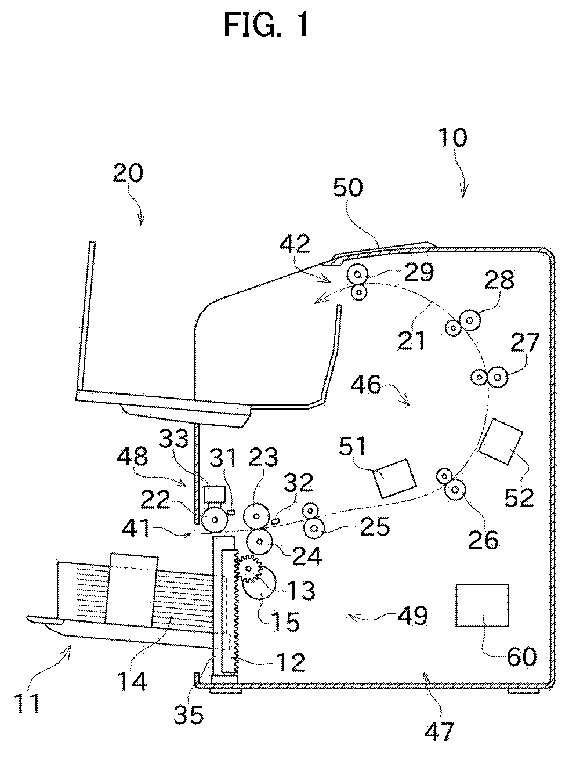
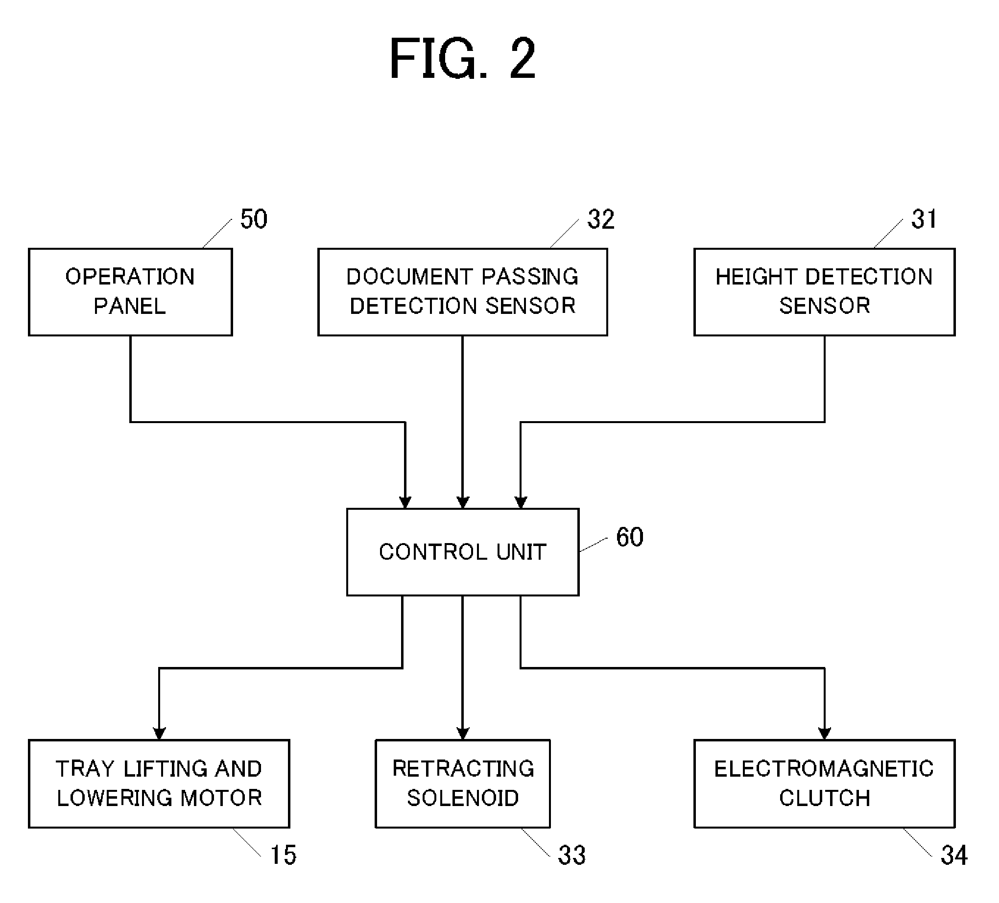
[0033]Preferred embodiments of the present invention will be described below. FIG. 1 is a sectional side view illustrating an entire configuration of an image scanner according to a preferred embodiment of the present invention, and FIG. 2 is a block diagram illustrating a portion of an electronic configuration of the image scanner. FIG. 3 is an enlarged sectional side view illustrating a state in which a transfer unit is driven to transfer a topmost document into a document transportation path. FIG. 4 is an enlarged sectional side view illustrating a state in which a pickup roller is retracted upward immediately before the transfer of the topmost document is completed. FIG. 5 is an enlarged sectional side view illustrating a state in which the transfer is completed to lower the pickup roller again. FIG. 6 is an enlarged sectional side view illustrating a state in which a document tray is elevated. FIGS. 7 and 8 are flowcharts illustrating document tray elevation control.

[0034]As il...


PUM


Abstract

In an image scanning apparatus, when documents on a document tray are sequentially transferred, different control steps are performed according to a scanning speed when an upper surface height of the documents is lowered thereby turning off a height detection sensor. In a first control mode, which is not a high speed scanning, the document tray is elevated little by little during an inter-transfer time between each time one document is transferred until the upper surface height reaches a target height that is higher by a predetermined distance since the height detection sensor is turned on. In a second control mode, in which high speed scanning is performed, the document tray is elevated little by little during the inter-transfer time each time the one document is transferred until the upper surface height reaches a height that is higher by a predetermined distance than a height at a time when the height detection sensor is turned off.

Description

CROSS-REFERENCE TO RELATED APPLICATIONS[0001]This application claims priority under 35 U.S.C. 119 to Japanese Patent Application No. 2007-67346, filed on Mar. 15, 2007, which application is hereby incorporated by reference in its entirety.BACKGROUND OF THE INVENTION[0002]1. Field of the Invention[0003]The present invention relates to a configuration of an image scanning apparatus suitably used to place and scan a large amount of documents.[0004]2. Description of the Related Art[0005]For example, Japanese patent Laid-Open application publication No. 2006-16093 discloses a copying machine which includes an upper limit position detection sensor for detecting a topmost document while being able to accommodate plural documents on a document tray (document feeder tray). In the copying machine disclosed in Japanese patent Laid-Open application publication No. 2006-16093, when the number of documents is decreased as the documents on the document tray are fed, a control device controls a tra...

Claims


Application Information

Patent Timeline
Patent Type & Authority Applications(United States)
IPC IPC(8): B65H7/02H04N1/04
CPCB65H1/14B65H2511/152H04N2201/0081H04N1/0062H04N1/00567B65H2801/39B65H2511/414B65H2511/20B65H2220/01B65H2220/02B65H2220/11B65H2511/15
Inventor OSHIMA, OSAMU
Owner MURATA MASCH LTD
Why Eureka
Try Eureka