
Delay line interferometer having a stepped delay element

a delay element and delay line technology, applied in the field of delay line interferometers, can solve the problems of reducing decision quality and distortion of signals

Inactive Publication Date: 2008-09-18
OPNEXT SUBSYST
View PDF25 Cites 24 Cited by
  • Summary
  • Abstract
  • Description
  • Claims
  • Application Information

AI Technical Summary

Benefits of technology

[0015]In another preferred embodiment, the present invention is a method in a delay line interferometer for differentially demodulating an optical input signal, comprising: splitting the input signal into two signal paths having a transit time difference for providing a differentially demodulated signal to at least one of constructive and destructive outputs; delaying a signal traversing a positionable delay element along a first direction in one of the signal paths with a selected optical delay dependent on a position of the delay element in a second direction; and positioning the delay element in the second direction for controlling the transit time difference.
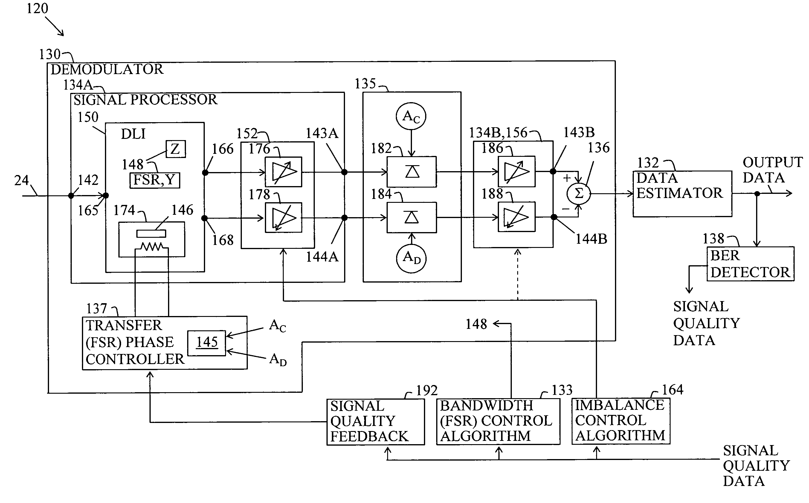
[0018]In a preferred embodiment, the present invention is an optical receiver, comprising: a signal processor having constructive and destructive transfer functions for receiving a modulated optical input signal and issuing signals at constructive and destructive outputs, respectively; at least one transfer phase element disposed in the signal processor, the transfer phase element for providing a controllable transfer function phase for at least one of the transfer functions with respect to a frequency of the input signal; and a transfer phase controller coupled to the transfer phase element for controlling the transfer function phase for maximizing a difference between signal powers for the constructive and destructive outputs.

Problems solved by technology

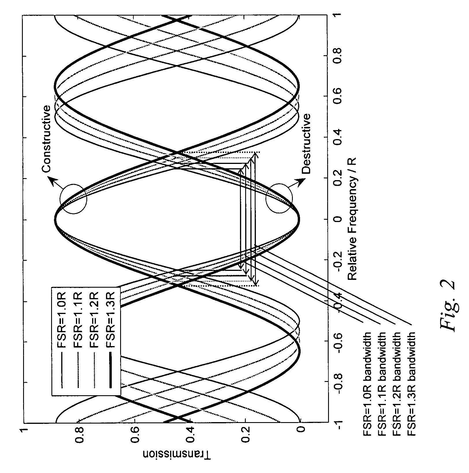
The ISI causes distortion of the signal and reduces the decision quality (the ability to accurately detect if a bit is a logical “1” or “0”) at a receiver.

Method used


Image

  • Delay line interferometer having a stepped delay element
  • Delay line interferometer having a stepped delay element
  • Delay line interferometer having a stepped delay element

Examples


Embodiment Construction

[0042]The details of preferred embodiments and best mode for carrying out the ideas of the invention will now be presented. It should be understood that it is not necessary to employ all of the details of the preferred embodiments in order to carry out the idea of the invention. It should be further understood that the details of the preferred embodiments may be mixed and matched for carrying out the invention. Therefore, these details should be viewed for understanding the idea of the invention but should not to be read as limitations of the idea that is expressed in the below listed claims.

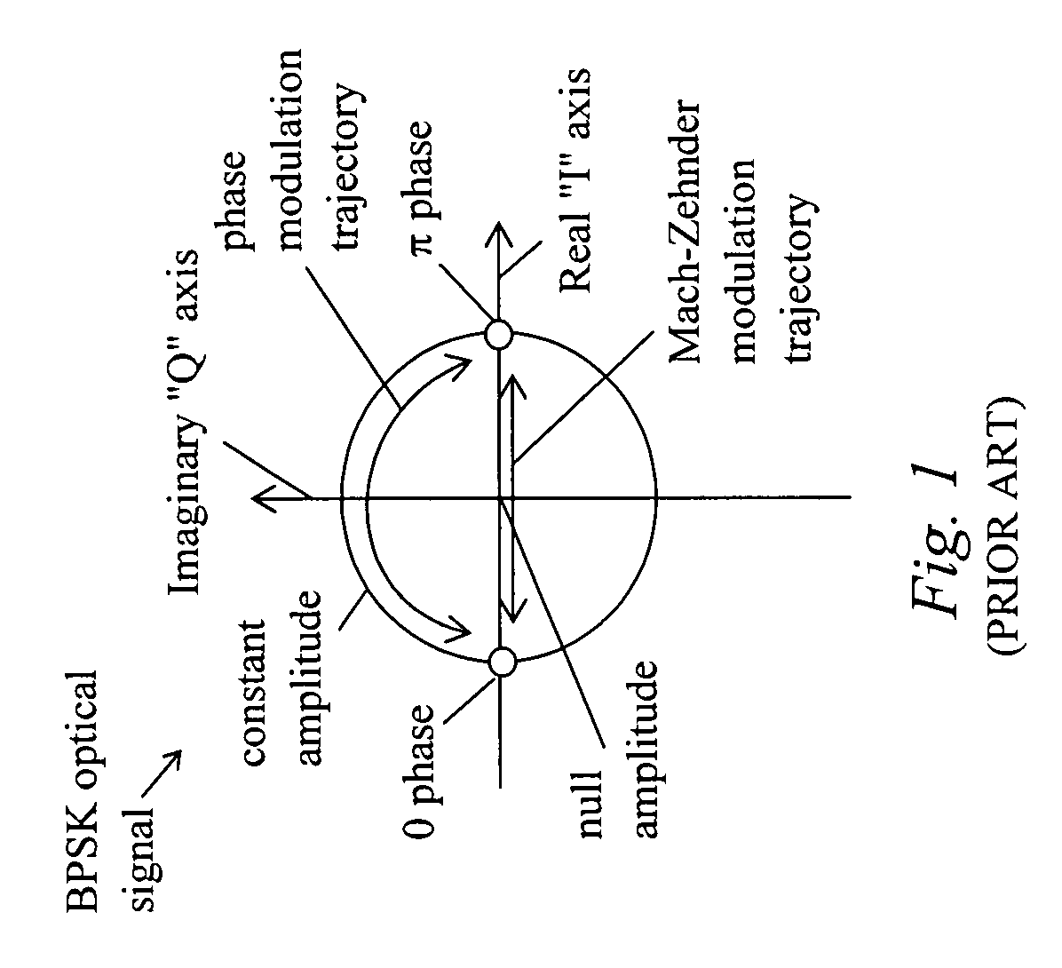
[0043]The preferred embodiments are described in terms of binary phase shift keyed (BPSK) signals using a differentially-encoded BPSK (DeBPSK, or DPSK) modulation format. However, the idea of the invention may be carried out with higher order modulation formats such as quadrature phase shift keyed (QPSK), 4QAM, 8PSK, 16QAM and so on. For example, the idea can be carried out with differentially-e...


PUM


Abstract

An optical receiver apparatus and methods for mitigating intersymbol interference (ISI) in a differentially-encoded modulation transmission system by controlling constructive and destructive transfer functions. The receiver includes a bandwidth control element for controlling transfer function bandwidth, a transfer phase controller for controlling transfer function phase and / or an imbalancer for imbalancing the transfer functions for compensating for intersymbol interference and optimizing the quality of the received optical signal.

Description

CROSS REFERENCE TO RELATED APPLICATION[0001]This application is a continuation-in-part of pending application Ser. No. 11 / 724,017 filed Mar. 14, 2007 by the same inventors for the same assignee.BACKGROUND OF THE INVENTION[0002]1. Field of the Invention[0003]The present invention relates to apparatus and methods for adjusting constructive and destructive transfer functions of a differentially encoded phase shift keyed receiver for reducing inter-symbol interference in optical systems.[0004]2. Description of the Prior Art[0005]For an optical system with filters, the effective concatenated bandwidth of the filters induces intersymbol interference (ISI). The ISI causes distortion of the signal and reduces the decision quality (the ability to accurately detect if a bit is a logical “1” or “0”) at a receiver. This decision quality may be quantified by counting the number of error bits and dividing it by the total number of transmitted bits. The resulting ratio is called bit error ratio (B...

Claims


Application Information

Patent Timeline
IPC IPC(8): G02F2/00
CPCH04B10/675H04L1/205H04B10/677
Inventor HEFFNER, BRIAN L.MALOUIN, CHRISTIANSCHMIDT, THEODORE J.
Owner OPNEXT SUBSYST
Learn More