Dental machining unit with tool spindle

a technology of machining unit and tool spindle, which is applied in the direction of bearings, drilling tools, diagnostics, etc., to achieve the effect of ensuring the necessary stability

Active Publication Date: 2008-09-18
SIRONA DENTAL SYSTEMS
View PDF11 Cites 41 Cited by
  • Summary
  • Abstract
  • Description
  • Claims
  • Application Information

AI Technical Summary

Benefits of technology

[0015]In this context it is of advantage if three bracing members are uniformly distributed along the circumference. A result of the use of three bracing members distributed uniformly over the circumference is that, in particular, detection of forces generated in the radial direction in terms of magnitude and direction is assured.
[0016]It is further of advantage if the bracing member is designed as a flat bracing member having a rectangular cross-section. The flat, rectangular design variant assures the necessary stability for transmission of the spindle forces to the bearing housing. In addition, adequate flexibility of the respective bracing members is given with regard to the sensor members disposed thereon and deformation thereof for the purpose of detecting said forces.
[0017]It is also of advantage if each bracing member encloses an angle α of between 0° and 90°, especially between 30° and 60° with the center axis. The choice of the value of α governs the ra

Problems solved by technology

Due to the time difference existing between the occurrence of a change in the cutting or grinding force generated on t

Method used


Image

  • Dental machining unit with tool spindle
  • Dental machining unit with tool spindle
  • Dental machining unit with tool spindle

Examples


Embodiment Construction

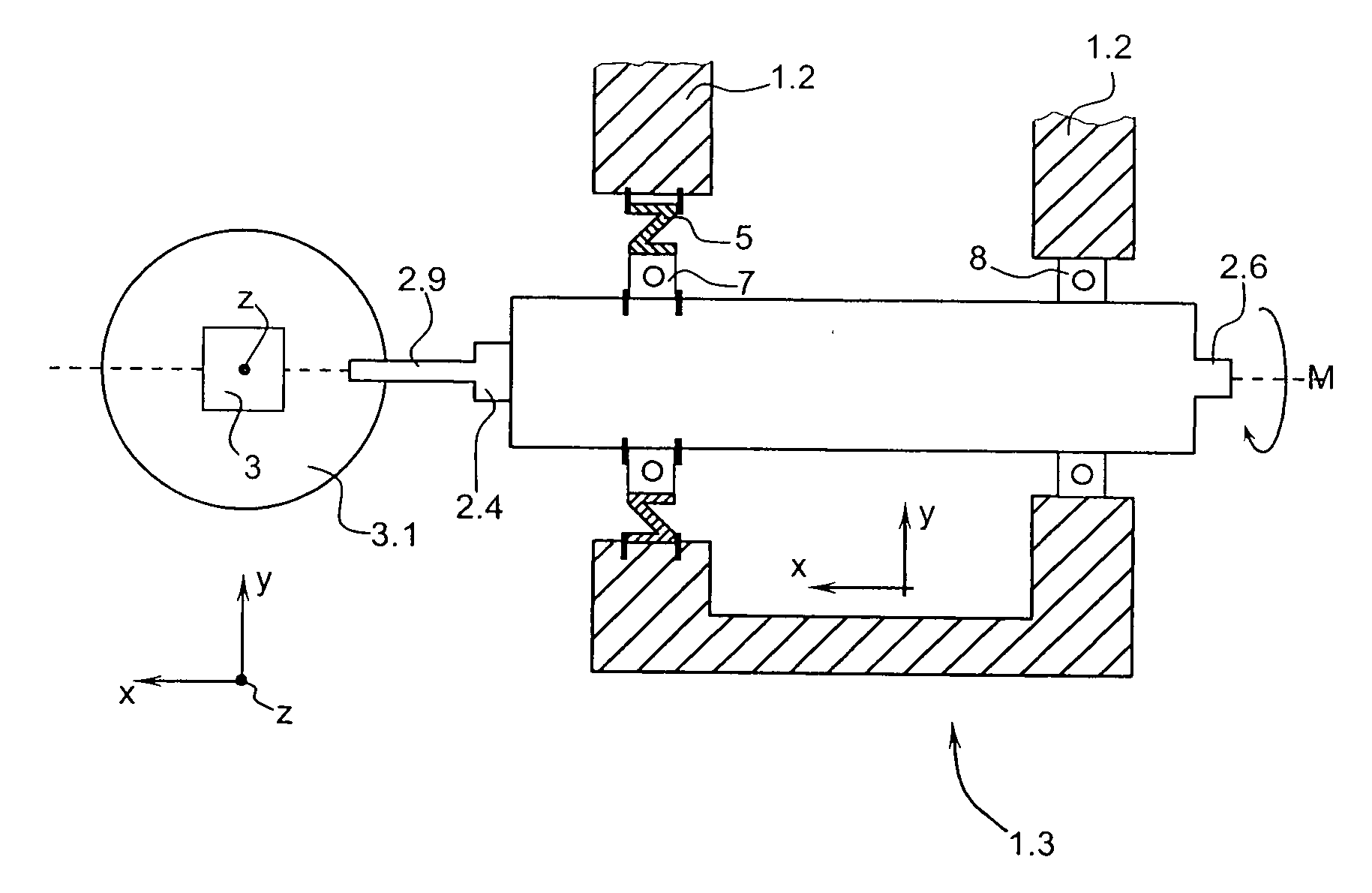
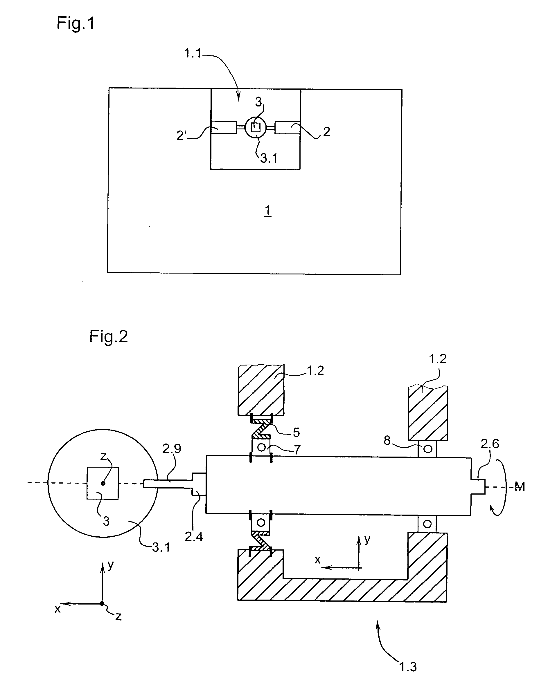
[0028]FIG. 2 is a schematic representation of the bearings of a tool spindle 2 of dental machining apparatus 1 as shown in FIG. 1. The tool spindle 2 has a chuck system 2.4 at its end facing a workpiece 3 to accommodate a tool 2.9 which extends into the machining chamber 1.1.

[0029]The tool spindle 2 is held in a spindle holder 1.3 of the machining apparatus 1 via a bearing housing 1.2. The spindle holder 1.3 holding the tool spindle 2 can be moved together with the tool 2.9 in a direction X toward the workpiece 3 and away from it and can also be moved in the direction Y transversely to the tool 2.5. This is indicated by the arrows in the X and Y directions. The workpiece 3 is held in a workpiece holder 3.1 that can be driven in the direction Z.

[0030]The tool spindle 2 is mounted on the housing side in a bearing housing 1.2 substantially immovably axially and radially in order to perform very precise machining operations on the workpiece 3.

[0031]The tool spindle 2 is driven by a moto...


PUM

PropertyMeasurementUnit
Angleaaaaaaaaaa
Angleaaaaaaaaaa
Angleaaaaaaaaaa

Abstract

The present invention relates to dental machining apparatus (1) for blanks (3) comprising a tool spindle (2) having an axis of rotation (2.8) and mounted in a bearing housing (1.2) disposed on the machine housing side. A force sensor (5) is also provided, which is disposed between the tool spindle (2) and the bearing housing (1.2) for the purpose of detecting the machining force acting on the tool spindle (2), wherein the tool spindle (2) can be supported against the bearing housing (1.2) directly or indirectly via the force sensor (5).

Description

TECHNICAL FIELD [0001]The invention relates to dental machining apparatus with a tool spindle having an axis of rotation and a bearing housing to hold the tool spindle and shaft respectively, including shaft bearings.DESCRIPTION OF THE PRIOR ART [0002]In dental machining apparatus known hitherto, the machining or cutting force of the tool is determined indirectly via the current uptake of the motors. Due to the time difference existing between the occurrence of a change in the cutting or grinding force generated on the tool and the subsequent change in current, a dead time occurs during measurement processes, resulting in inaccuracy.[0003]It is an object of the invention to design and arrange a dental machining apparatus with a tool spindle such that optimal detection of the forces acting on the tool is assured.SUMMARY OF THE INVENTION [0004]The problem is solved by the invention by providing a force sensor disposed between the tool spindle and the bearing housing so as to record th...

Claims


Application Information

Patent Timeline
IPC IPC(8): B23C1/00
CPCA61B17/1626A61B19/46A61B2017/00017A61B2019/464A61C1/00Y10T409/306944A61C19/04G01L1/2231G01L5/0019Y10T409/309352A61C1/185A61B2090/064A61B90/06F16C19/522F16C27/04F16C2316/13
Inventor HASENZAHL, THOMAS
Owner SIRONA DENTAL SYSTEMS
Why Eureka
Try Eureka