Wireless Communication System and Wireless Communication Method

a wireless communication and wireless communication technology, applied in wireless communication, transmission path sub-channel allocation, transmission path division, etc., can solve the problems of complicated device configuration and complicated device configuration, and achieve the effect of reducing the rate of contention channel collisions

Active Publication Date: 2008-09-18
DAINGEAN TECH LTD
View PDF18 Cites 46 Cited by
  • Summary
  • Abstract
  • Description
  • Claims
  • Application Information

AI Technical Summary

Benefits of technology

[0007]The present invention has been made to solve the problems, and an object of the present invention is to provide a radio communications system and a radio communications method that are capable of readily reducing the rate of collisions of contention channels.

Problems solved by technology

In Non-Patent Document 1, dividing the contention data into preamble and message sections requires complicated control, and thus requires complicated device configuration.
The technique of Patent Document 1 also requires complicated control in order to separately manage the time slots so as to avoid collisions of contention channels, and thus also requires complicated device configuration

Method used


Image

  • Wireless Communication System and Wireless Communication Method
  • Wireless Communication System and Wireless Communication Method
  • Wireless Communication System and Wireless Communication Method

Examples


first preferred embodiment

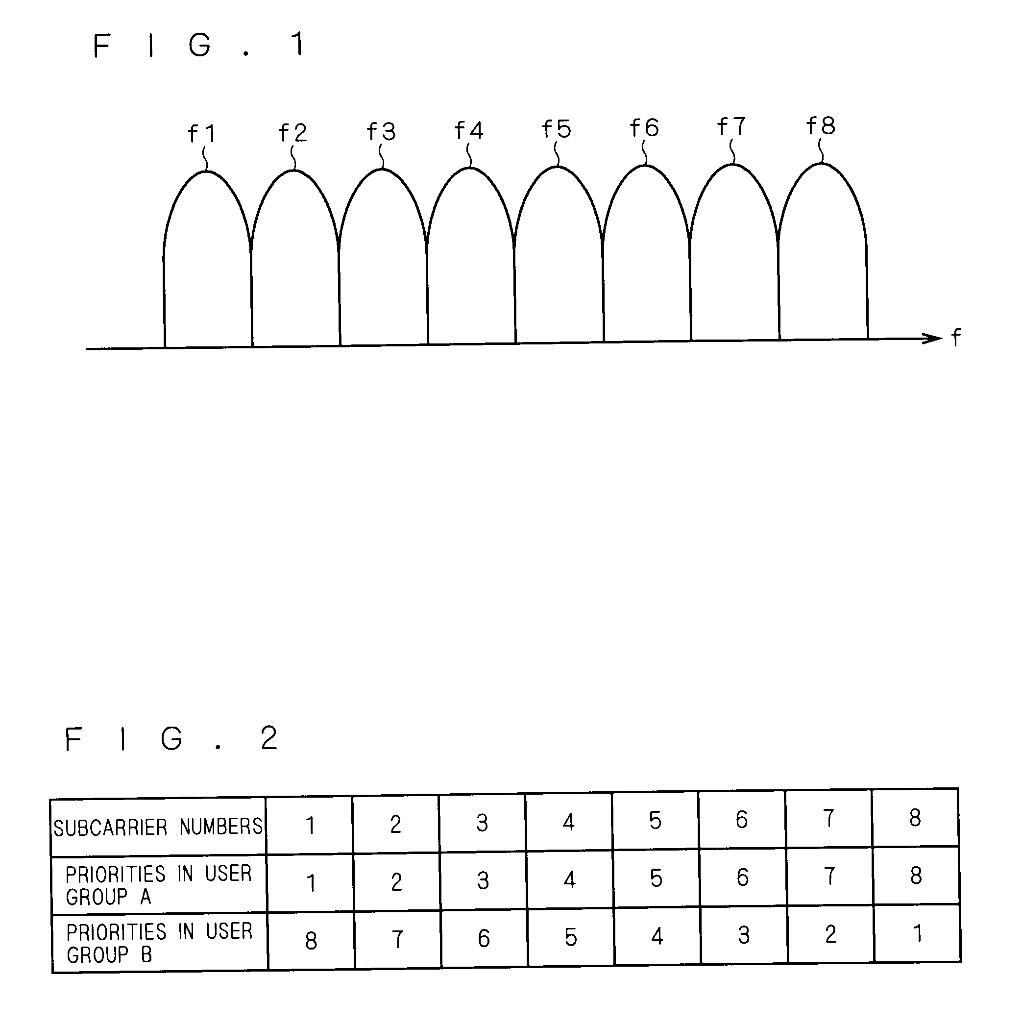
[0048]FIGS. 1 and 2 are schematic diagrams illustrating the operation of a radio communications system (a radio communications method) according to a first preferred embodiment. FIG. 1 shows an example in which subcarriers f1 to f8 are frequency bands of the FDM. The subcarriers f1 to f8 are assigned by a single base station to a plurality of mobile stations that are subordinate to the base station. In this specification, it is assumed that the subcarriers fn (n: an integer) have unique subcarrier numbers “n”, and that the subcarrier numbers are assigned in ascending order from the lowest frequency to the highest frequency in the frequency domain.

[0049]In FIG. 2, a plurality of mobile stations are classified into two kinds of user groups A and B, and the user groups A and B are respectively assigned the priorities of the subcarriers f1 to f8. The user groups A and B are classified on the basis of information like user IDs unique to the mobile stations, their telephone numbers, etc. ...

second preferred embodiment

[0083]In general, the subcarriers in a multi-carrier scheme (FDM or OFDM) have a transmission path characteristic that depends on frequency. The transmission path characteristic may therefore be considered when assigning the subcarriers as radio resources.

[0084]FIG. 11 is a diagram illustrating the assignment of subcarriers in a radio communications system according to a second preferred embodiment. In FIG. 11, the bands 310 and 330 have high communication quality (receiving sensitivity), and the band 320 has low communication quality. In this case, the quality of communications can be enhanced by preferentially using the bands 310 and 330 as radio resources, than using the band 320 (by assigning the series of subcarriers 340 and the series of subcarriers 350). In this specification, an arrangement of a plurality of subcarriers at equal intervals in the frequency domain is referred to (simply) as a series of subcarriers.

[0085]The transmission path characteristic can be estimated, in...

third preferred embodiment

[0107]The subcarriers used as radio resources may be designated by their subcarrier numbers that are allocated to a plurality of subcarriers arranged at equal intervals in the frequency domain (a series of subcarriers) in ascending order from the lowest frequency to the highest frequency, or they can be designated by subcarrier allocation information including given parameters, etc.

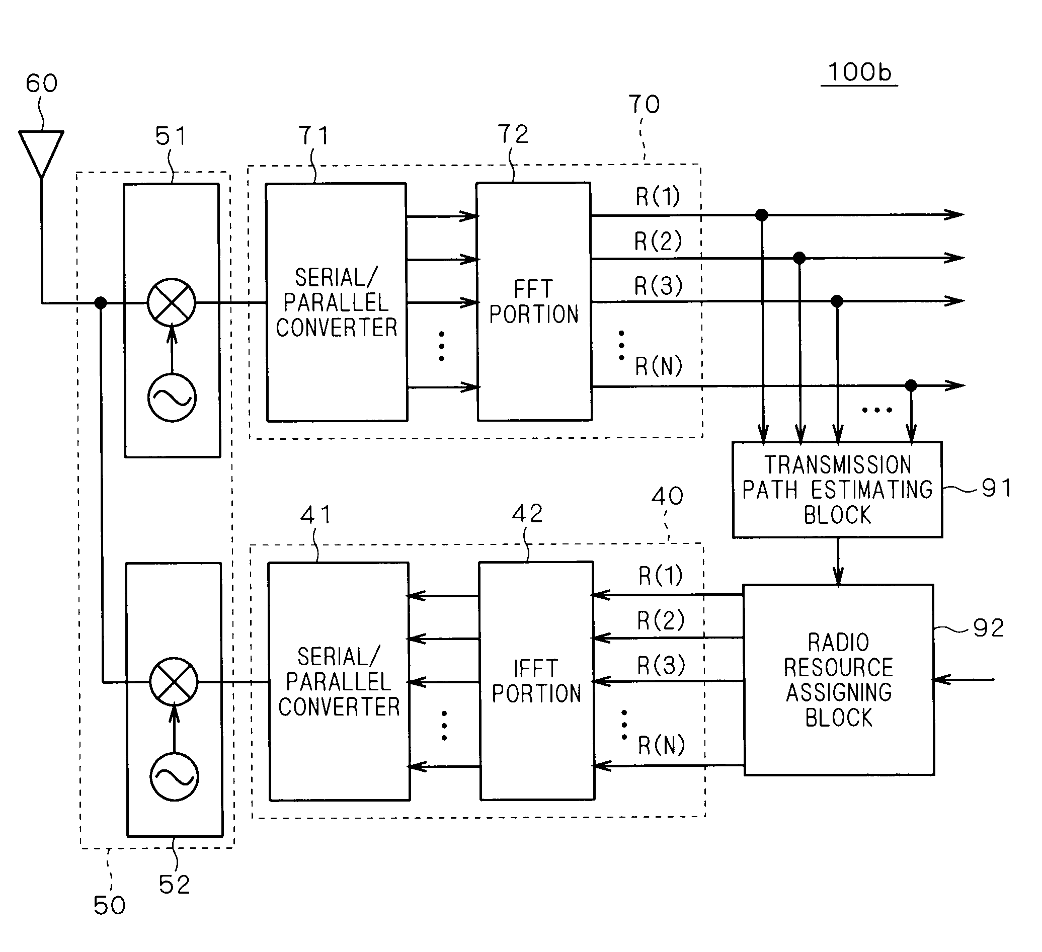
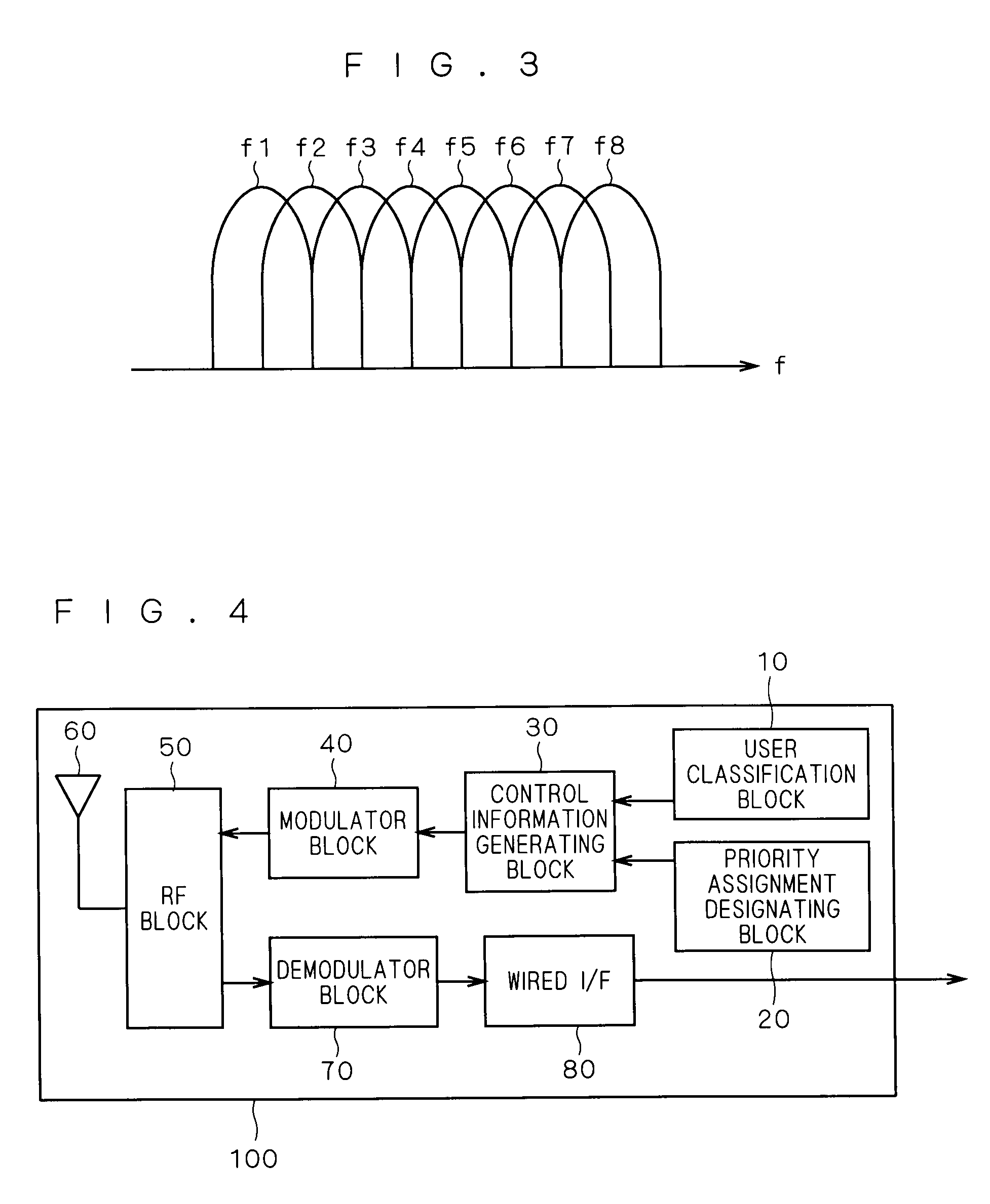
[0108]FIG. 16 is a block diagram illustrating the functions of a base station 100c in a radio communications system according to a third preferred embodiment. As compared with FIG. 4, the configuration of FIG. 16 includes a subcarrier allocation information storing block 93 that inputs the subcarrier allocation information to the modulation block 40 (some parts are not shown for the sake of convenience). The subcarrier allocation information storing block 93 stores subcarrier allocation information that contains given parameters etc. for designating the subcarriers used as radio resources. The subcarrier ...


PUM


Abstract

The present invention relates to a radio communications system and a radio communications method, and an object of the invention is to readily reduce the occurrence of collisions of contention channels. In order to achieve the object, radio resources are assigned in different orders between one radio communication and another one radio communication.

Description

TECHNICAL FIELD[0001]The present invention relates to a radio communications system and a radio communications method, and particularly to a technique for simplifying device configuration.BACKGROUND ART[0002]Conventionally, in multi-carrier radio communications using a plurality of subcarriers, a mobile station sends, prior to data transmission, a request for permission to transmit data, by using a contention channel to the base station, and acquires a subcarrier after receiving permission. As to the contention channels, some schemes are proposed for avoiding collisions of pieces of contention data sent from a plurality of mobile stations, including a scheme that assigns time slots to individual mobile stations, and a scheme that divides the contention data into preamble and message sections, such that a mobile station sends the message section after having confirmed radio resource availability by receiving ACK / NACK etc. as a response to the preamble section (W-CDMA scheme). Such a ...

Claims


Application Information

Patent Timeline
Patent Type & Authority Applications(United States)
IPC IPC(8): H04Q7/20H04B7/24H04W72/04H04W74/08
CPCH04J13/16H04L5/0007H04L5/0016H04L5/0037H04W72/08H04L5/006H04L5/0064H04W72/0453H04L5/0053H04W72/54
Inventor SUEMITSU, TAISEISUZUKI, KUNIYUKI
Owner DAINGEAN TECH LTD
Why Eureka
Try Eureka