
Electrical connector for an in-body multi-contact medical electrode device

a multi-contact, electrical connector technology, applied in the direction of coupling device connection, application, diagnostic recording/measuring, etc., can solve the problems of large size of the connector in the prior art, difficult organization and management, bulky appearance of the connector, etc., to minimize the space in which the opening and closing movement occurs, and ensure the electrical contact reliable

Active Publication Date: 2008-09-18
TECH MEDICAL INSTR
View PDF20 Cites 4 Cited by
  • Summary
  • Abstract
  • Description
  • Claims
  • Application Information

AI Technical Summary

Benefits of technology

The connector provides a compact, reliable, and secure electrical connection that withstands involuntary motions, ensuring consistent data collection and improved contact reliability between the electrode tail and conductors.

Problems solved by technology

Some connectors in the prior art are large in size and clumsy making them difficult to organize and manage.
Certain prior art connectors utilized a flat ribbon-type cable that emerged laterally off the top of the connector giving the connector a bulky appearance.
Some connectors in the prior art may create concerns with reliability of the connection.
If a connector fails during use all of the information obtained may be lost or rendered inaccurate.
If a patient has a seizure there is the chance that the electrical connections could be destroyed or disrupted.
The spring-loaded ball plunger devices of the prior art have disadvantages.
This directly effects the ability of the ball to contact the tail receiving void possibly leading to an inaccurate contact.
The very nature of the movement of the ball across the contact of the plural-contact tail means there is potential for an inaccurate and unreliable contact.
In summary, there are a number of problems and shortcomings in prior connectors for use with multi-contact medical electrode devices.

Method used


Image

  • Electrical connector for an in-body multi-contact medical electrode device
  • Electrical connector for an in-body multi-contact medical electrode device
  • Electrical connector for an in-body multi-contact medical electrode device

Examples


Embodiment Construction

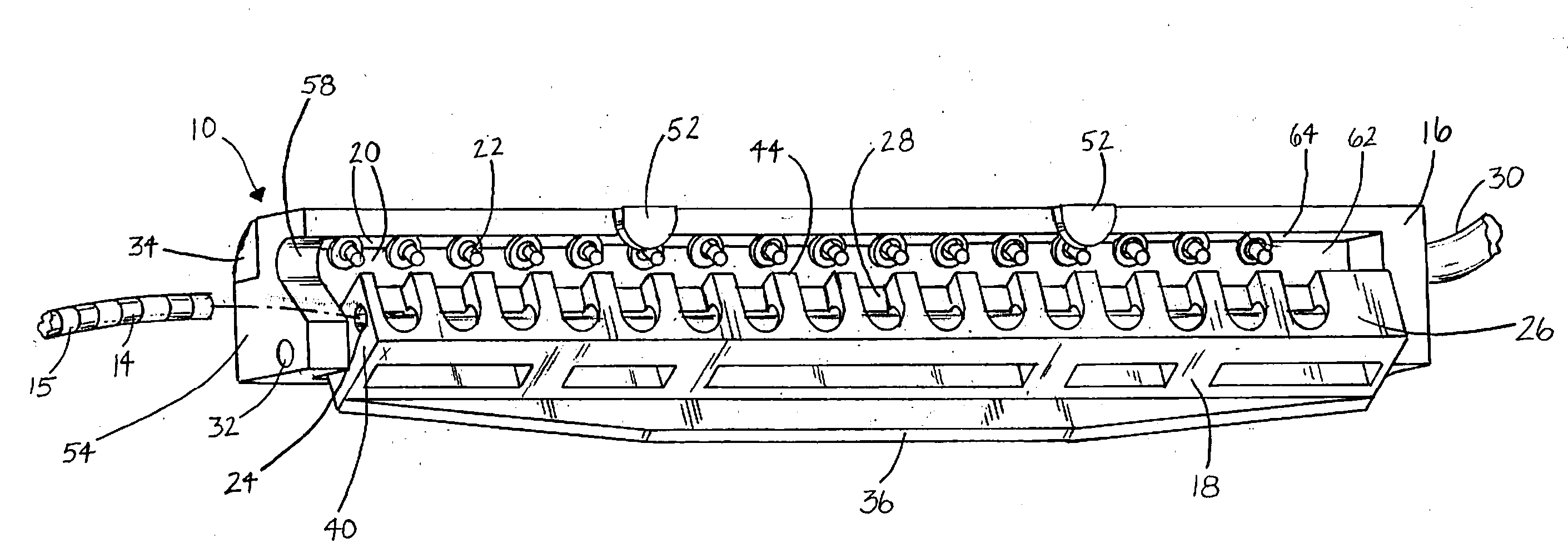
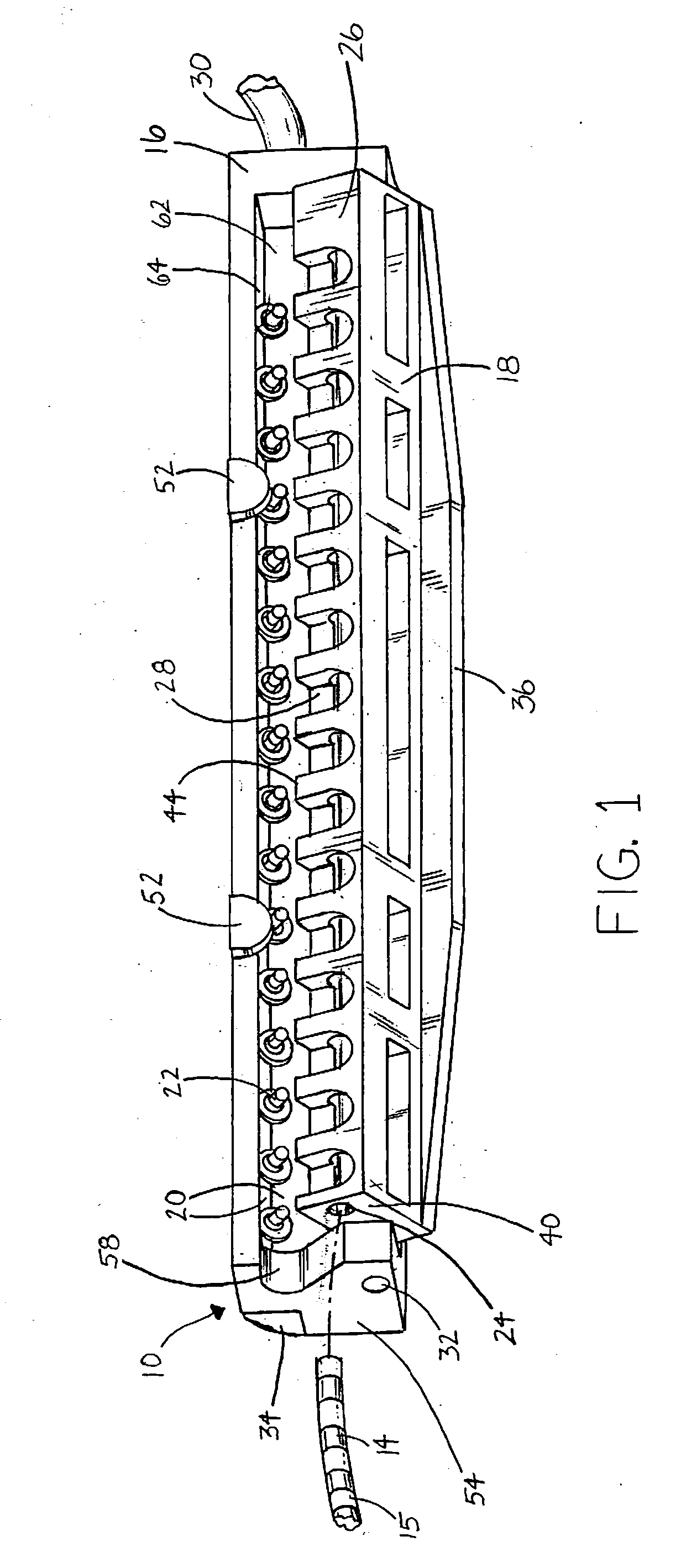
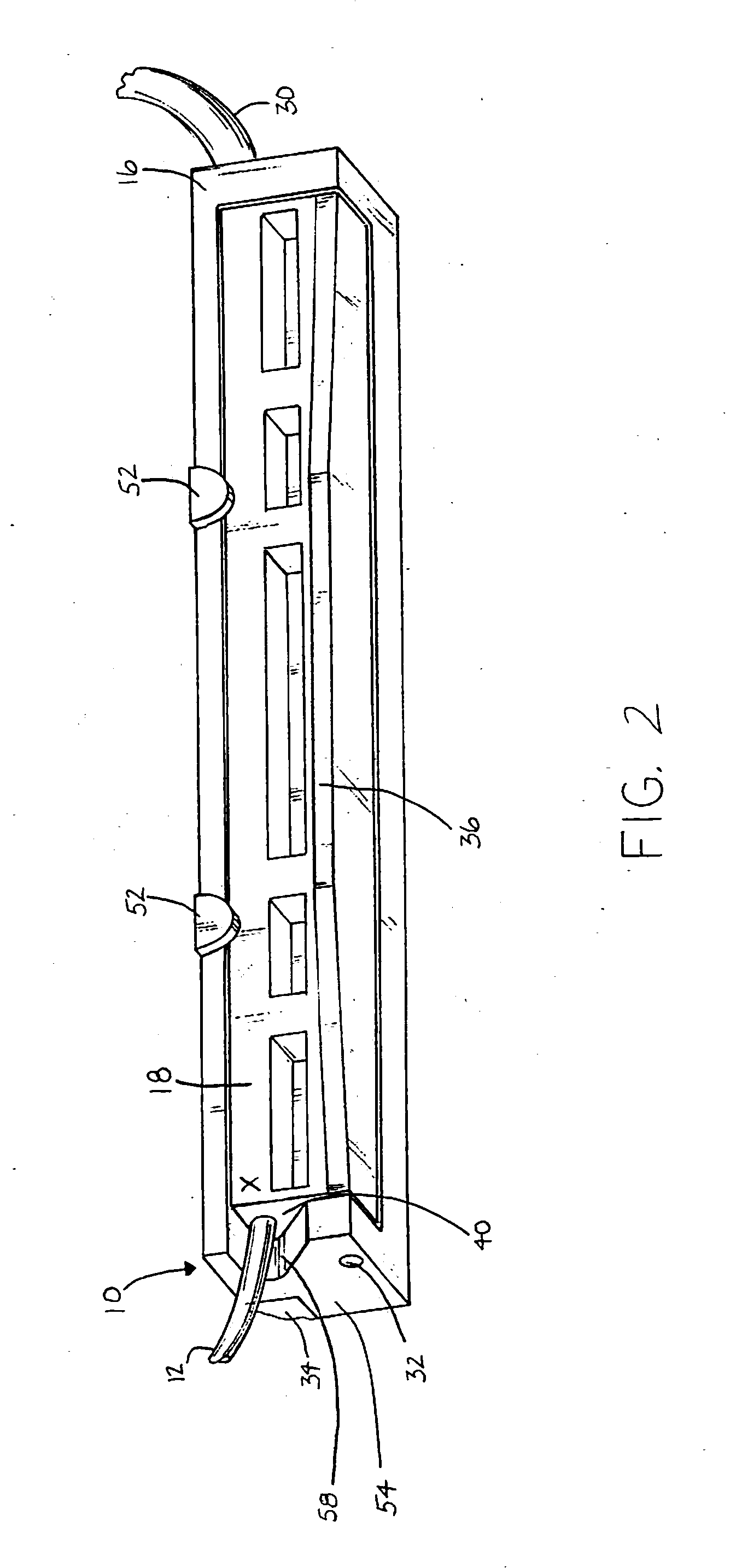
[0039]FIGS. 1-6 illustrate an electrical connector 10 for connecting the linear-array plural-contact tail 12 of an in-body multi-contact medical electrode (the in-body portion of which is not shown), having a linear array of electrical contacts 14 spaced therealong, each electrically linked by a small electrical wire running up and beyond tail 12 to a particular in-body contact on the in-body portion of the electrode. Connector 10 includes first and second elongate members 18 and 16 which are pivotable with respect to one another about a pivot axis A which extends along their lengths.

[0040]Second elongate member 16 has a nesting surface 20 which includes two faces set at right angles to one another, a pivot-axis-adjacent face 62 and a pivot-axis-opposite face 64. A linear array of spring-loaded pin plunger devices 22 are situated along the nesting surface 20 at the intersection of the pivot-axis-adjacent face 62 and pivot-axis-opposite face 64 and extend at an angle substantially pa...


PUM


Abstract

An improved electrical connector for connecting a multi-contact medical electrode device with a plural-contact tail. Having a tail-receiving first elongate member with a tail-receiving void and a second elongate member. The second elongate member has a nesting surface and an array of electrical conductors which are spring-loaded pin plunger devices. The spring-loaded pin plunger devices having movable pins that project into and at least partially, preferably halfway, across and into the tail-receiving void. The device is configured such that the spring-loaded pin plunger devices extend at an angle substantially parallel to the movement of the tail-receiving void at the point the pin tips enter therein. The distal end of the second elongate member has an opening through which a multi-wire electrical cable extends. The second elongate member also has a channel in alignment with the opening that has therein the multiple wires of the electrical cable.

Description

FIELD OF THE INVENTION[0001]This invention is related generally to electrical connectors for use in the medical field and, more particularly, to medical connectors for implantable multi-contact medical electrode devices.BACKGROUND OF THE INVENTION[0002]Multi-contact medical electrode devices are placed in the human body for various purposes, such as brain-mapping in epilepsy treatment. In such treatments wires generally extend from the multi-contact medical electrode to a plural-contact tail. The plural-contact tail is linear in shape and contains an array of sleeve-like contacts spaced therealong. The plural contacts of the plural-contact tail are to facilitate quick electrical connection of the contacts of the multi-contact medical electrode device such as for monitoring, recording and analysis purposes. Connectors have been configured to simultaneously engage the contacts of the plural-contact tail for their individual electrical connection to separate wire strands which emerge f...

Claims


Application Information

Patent Timeline
Patent Type & Authority Applications(United States)
IPC IPC(8): A61B5/04
CPCH01R13/2421H01R13/5224H01R2201/12H01R2107/00H01R24/58Y10S439/909
Inventor PUTZ, DAVID A.
Owner TECH MEDICAL INSTR
Learn More