Method and means for self calibrating a valid operating range

a self-calibration and operating range technology, applied in the direction of instruments, vehicle testing, structural/machine measurement, etc., can solve the problems of time-consuming and inconvenient calibration process, and achieve the effect of increasing the valid operating rang

Inactive Publication Date: 2008-09-18
DANFOSS POWER SOLUTIONS INC
View PDF12 Cites 3 Cited by
  • Summary
  • Abstract
  • Description
  • Claims
  • Application Information

AI Technical Summary

Benefits of technology

[0006]A method of calibrating a valid operating range. The steps include loading default calibration limits and then using an algorithm to monitor inputs for new calibration limits from an input device. Once the new calibration limits are received the algorithm detects if the new calibration limits provide a fault and if not the algorithm rescales an output based upon the new calibration limits to increase the valid operating range.

Problems solved by technology

Often when replacing these parts the calibration process used is time consuming and inconvenient.

Method used


Image

  • Method and means for self calibrating a valid operating range
  • Method and means for self calibrating a valid operating range
  • Method and means for self calibrating a valid operating range

Examples


Embodiment Construction

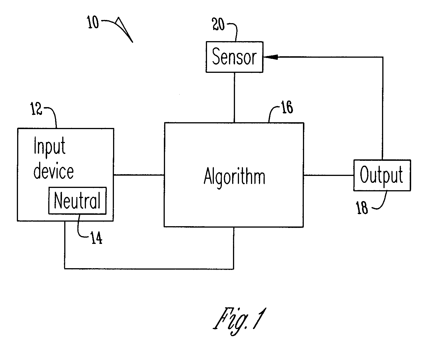
[0009]FIG. 1 shows a schematic diagram of a control system 10 for a device that requires calibration. In a preferred embodiment the control system 10 is for a tractor loader backhoe joystick wherein a replaceable mini joystick is provided. The control system 10 has an input device 12 with a neutral position 14 that provides an input to algorithm 16 that generates an output 18 and receives information from a sensor 20.

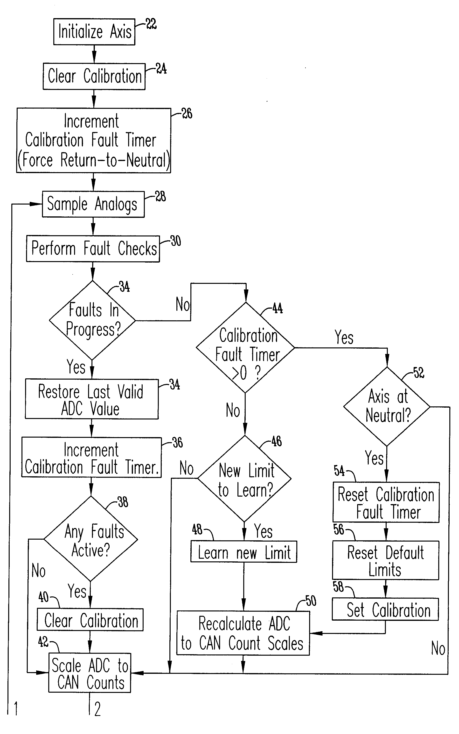
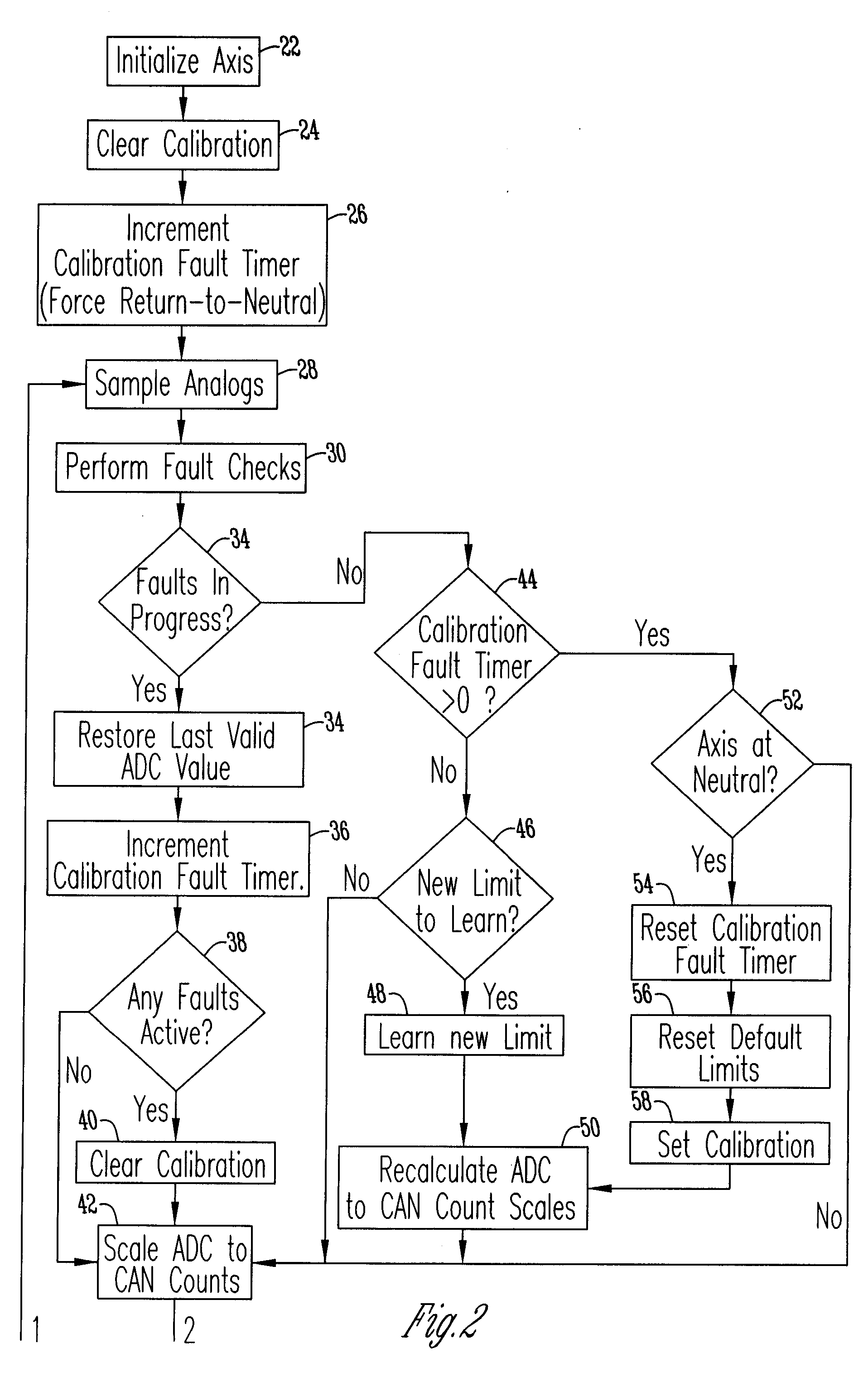
[0010]FIG. 2 shows a flow chart of algorithm 16. The process starts with step 22 wherein the algorithm initializes an axis. Then at step 24 the calibration is cleared such that default calibration limits are loaded. Then at step 26 an increment calibration fault timer is used to determine if the input device 12 needs to be returned to neutral. Thus, from this input sample analogs are provided at step 28 to provide output 18.

[0011]At step 30 a fault check is performed. First, the algorithm makes a decision 32 regarding whether faults are in progress. If faults are in pro...


PUM


Abstract

A method of calibrating a valid operating range. The method includes loading a default calibration limit and then monitoring an input for new calibration limits provided by an input device. An algorithm then detects if the new calibration limits provide a fault and if not the algorithm rescales the output based upon the new calibration limits to increase the valid operating range.

Description

BACKGROUND OF THE INVENTION[0001]This disclosure relates to a method and means for a calibration process. More specifically, this disclosure relates to a precise control for a mini joystick or the like.[0002]When a device has replaceable parts that have inconsistent tolerances, electrical and mechanical calibration is needed. Often when replacing these parts the calibration process used is time consuming and inconvenient.[0003]Thus, a principal object of the present invention is to provide an improved control system that is self calibrating.[0004]Yet another object of the present invention is to provide a method of calibration that eliminates the need for complex calibration processes.[0005]These and other objects, features, or advantages of the present invention will become apparent from the specification and claims.BRIEF SUMMARY OF THE INVENTION[0006]A method of calibrating a valid operating range. The steps include loading default calibration limits and then using an algorithm to...

Claims


Application Information

Patent Timeline
Patent Type & Authority Applications(United States)
IPC IPC(8): G06F7/00G06F3/038
CPCG06F3/0338
Inventor SPRANGER, BRIAN E.
Owner DANFOSS POWER SOLUTIONS INC
Why Eureka
Try Eureka