Vehicle power inhibiter

a technology of power inhibitor and vehicle, which is applied in the direction of anti-theft devices, instruments, analogue processes for specific applications, etc., can solve the problems of severely lacking vehicle control systems in a variety of aspects, and limit the rotational speed or revolutions per minute of the engine of the vehicl

Inactive Publication Date: 2008-09-18
WHITE STEVEN C +1
View PDF10 Cites 56 Cited by
  • Summary
  • Abstract
  • Description
  • Claims
  • Application Information

AI Technical Summary

Benefits of technology

[0039]Another embodiment of the present invention provides a method of limiting power of a vehicle having a drive-by-wire system. The method includes: allowing a user to control a first mode of operation of the drive-by-wire system and a second mode of operation of the drive-by-wire system; supplying an electronic circuit with a transducer voltage in the first mode of operation; and supplying the electronic circuit with the transducer voltage when the transducer voltage is less than a set voltage and with the set voltage when the transducer voltage is greater than or equal to the set voltage in the second mode of operation.
[0040]In one embodiment, the method further includes: allowing the user to control a third mode of operation of the drive-by-wire system; and supplying the electronic circuit with an idle voltage in the third mode of operation.
[0041]In one embodiment, the electronic circuit may be an electronic control unit (ECU) of the vehicle.
[0042]Another embodiment of the present invention provides a system for inhibiting power of a vehicle given to a third party. The system includes a mode-indicating device; and a power inhibiting device coupled to the mode-indicating device and adapted to selectively inhibit the power of the vehicle, the power inhibiting device comprising a voltage control circuit adapted to switch between a first part of the voltage control circuit adapted to supply an electronic control unit (ECU) of the vehicle with a voltage to increase the power of the vehicle when the voltage is less than a set voltage and with the set voltage when the transducer voltage is greater than or equal to the set voltage and a second part of the voltage control circuit adapted to supply the ECU of the vehicle with the voltage to increase the power of the vehicle. Here, the mode-indicating device is adapted to communicate a power restriction signal to the power inhibiting device to inhibit the power of the vehicle upon an activation of the mode-indicating device by a driver and until a deactivation of the mode-indicating device by the driver.
[0043]In one embodiment, the voltage control circuit is electrically coupled between the ECU of the vehicle and a transducer of an accelerator of the vehicle. The first part of the voltage control circuit may include a first voltage limiter to limit a voltage to a first voltage limit and a second voltage limiter to limit a voltage to a second voltage limit. The first voltage limit may be adapted to limit the vehicle to be in an idle mode, and the second voltage limit may be adapted to limit the vehicle to be in a valet mode. Alternatively, the first part of the voltage control circuit may include a first power limiter to limit the power of the vehicle to a first power level and a second power limiter to limit the power of the vehicle to a second power level. The second power level may be higher in power than the first power level and lower in power than a full power level.

Problems solved by technology

However, vehicle control systems are severely lacking in a variety of aspects.
Accelerator pedal obstructing devices consequently limit a vehicle's engine rotational speed or revolutions per minute (“RPM”), such that the device operates as an anti-theft device.

Method used


Image

  • Vehicle power inhibiter
  • Vehicle power inhibiter
  • Vehicle power inhibiter

Examples


Embodiment Construction

[0064]In the following detailed description, only certain exemplary embodiments of the present invention are shown and described, by way of illustration. As those skilled in the art would recognize, the described exemplary embodiments may be modified in various ways, all without departing from the spirit or scope of the present invention. Accordingly, the drawings and description are to be regarded as illustrative in nature, and not restrictive.

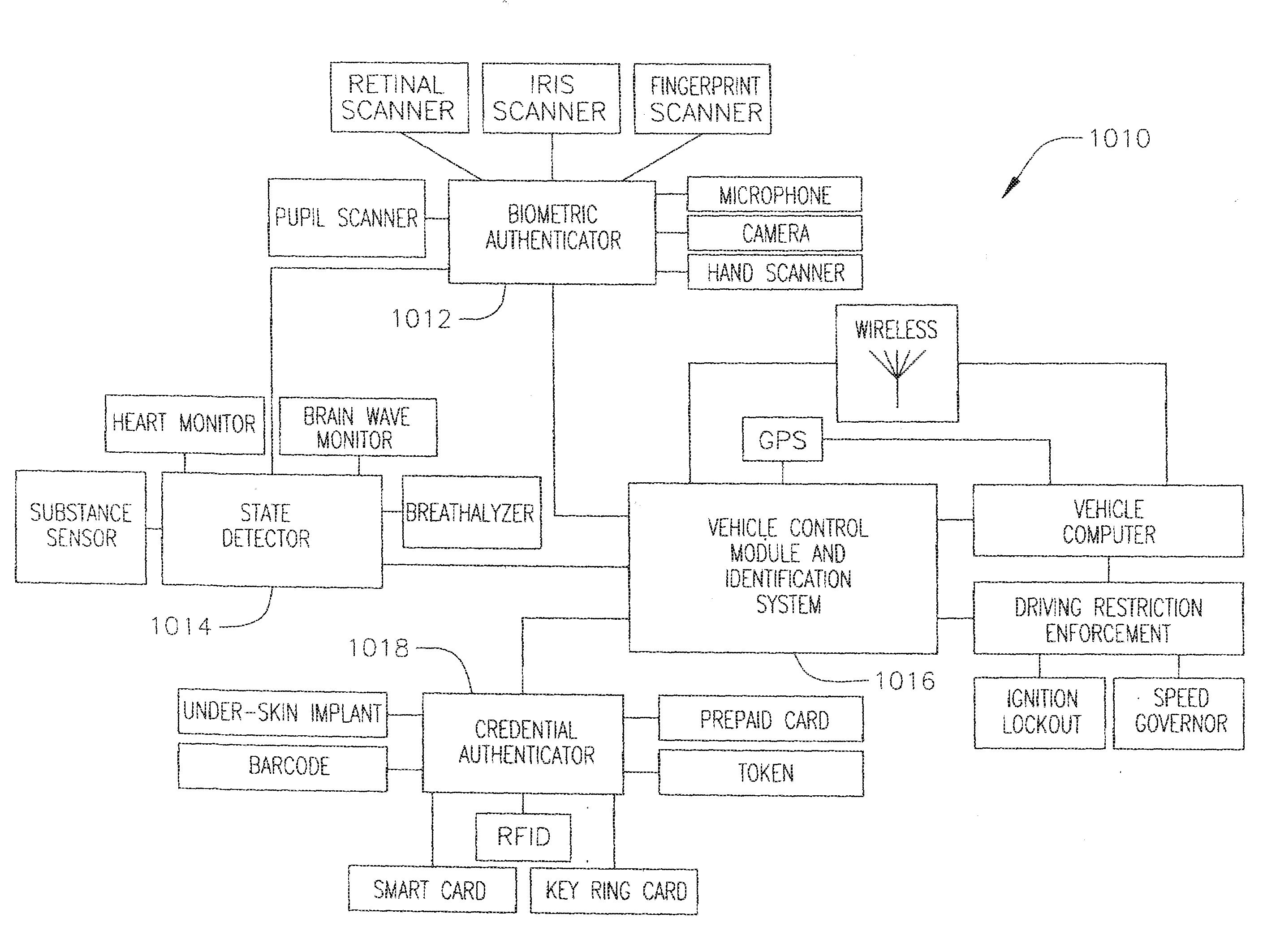
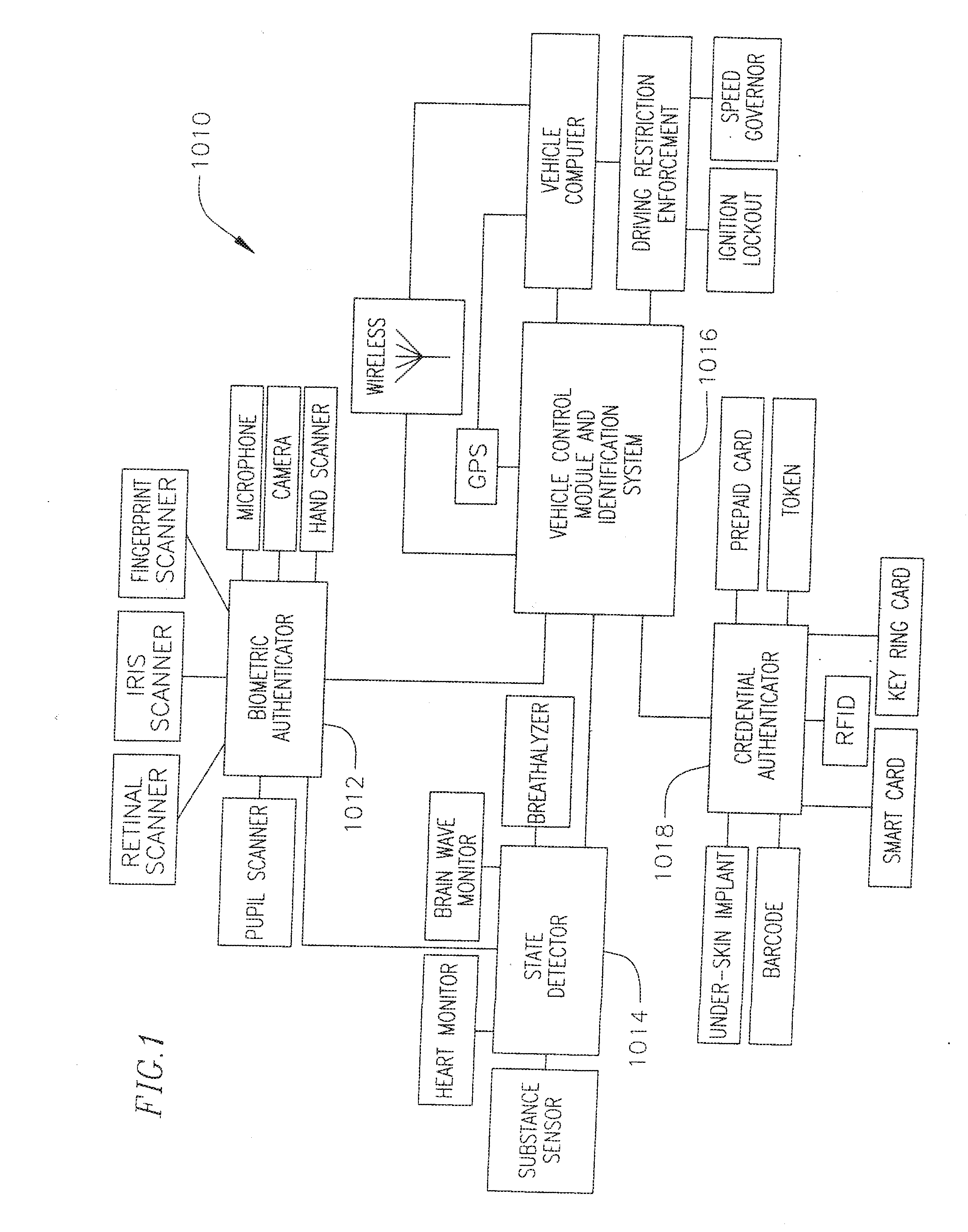
[0065]As envisioned in an embodiment of the present invention, a system provides theft protection, assures compliance with driving and / or licensing laws, offers customizable control for use by parents or when a vehicle is given to a third party such as a valet, service facility, designated driver, friend, or employee. The system further provides secure, encrypted, verifiable statistical information about a person's driving habits and who was driving at a particular time. The system may further restrict the driving of vehicles while under the ...


PUM


Abstract

A method and system for inhibiting power of a vehicle given to a third party. The system includes a mode-indicating, an authenticator coupled to the mode-indicating device, and a power inhibiting device coupled to the mode-indicating device and adapted to selectively inhibit the power of the vehicle. Here, the mode-indicating device is adapted to communicate a power restriction signal to the power inhibiting device to inhibit the power of the vehicle upon an activation of the mode-indicating device by an authenticated driver and until a deactivation of the mode-indicating device by the authenticated driver, and the authenticator is adapted to restrict the activation and the deactivation of the mode-indicating device unless the driver has been authenticated by the authenticator.

Description

CROSS-REFERENCE TO RELATED APPLICATION(S)[0001]This application claims priority to and the benefit of U.S. Provisional Application No. 60 / 789,822, filed on Apr. 5, 2006, the entire content of which is incorporated herein by reference.FIELD OF THE INVENTION[0002]The present invention relates to method and system for inhibiting power of a vehicle.BACKGROUND OF THE INVENTION[0003]The operation of a vehicle normally requires only a key. Anti-theft devices exist which add security based on a pass code. More advanced anti-theft devices exist to disable vehicles if biometric authentication, such as a fingerprint scan, is unsuccessful. However, vehicle control systems are severely lacking in a variety of aspects.[0004]For example, U.S. Pat. No. 5,586,457, which is herein incorporated by reference, discloses an accelerator pedal obstruction device located beneath an accelerator pedal that prevents and deters unauthorized use of a vehicle by limiting the vehicle to idle speed. Accelerator ped...

Claims


Application Information

Patent Timeline
Patent Type & Authority Applications(United States)
IPC IPC(8): G06F19/00G06F7/00B60R25/00B60R25/04
CPCB60K28/063B60R25/005B60R25/04B60R25/25B60R25/252B60W2550/402B60R25/257B60R2325/105B60W2540/22B60W2540/28B60R25/255B60W2540/043B60W2540/221B60W2556/50
Inventor WHITE, STEVEN C.WELLS, ROGER F.
Owner WHITE STEVEN C
Why Eureka
Try Eureka