Electromagnetic steel plate forming member, electromagnetic steel plate laminator, permanent magnet type synchronous rotating electric machine rotor provided with the same, permanent magnet type synchronous rotating electric machine, and vehicle, elevator, fluid machine, and processing machine using the rotating electric machine

a technology of electromagnetic steel plate laminator and electromagnetic steel plate, which is applied in the direction of magnetic circuit rotating parts, dynamo-electric machines, and magnetic circuit shape/form/construction. it is difficult to obtain large torque in the starting time and anisotropy is not used

Inactive Publication Date: 2008-09-25
YASKAWA DENKI KK
View PDF3 Cites 62 Cited by
  • Summary
  • Abstract
  • Description
  • Claims
  • Application Information

AI Technical Summary

Benefits of technology

[0029]With referring to the above problems, one or more embodiments of the invention provide an electromagnetic steel plate forming member, an electromagnetic steel plate laminator, a permanent magnet type synchronous rotating electric machine rotor provided with the same, a permanent magnet type synchronous rotating electric machine, and a vehicle, an elevator, a fluid machine, and a processing machine using the rotating electric machine, which saturation of q-axis flux may be suppressed in an outer iron core portion formed between upper surfaces of two magnet holes arranged in V-shape and an outer diameter of a rotor thereby to realize utilization of reluctance torque and improvement of magnet torque, and a large torque may be obtained in the starting time or in the starting abrupt change of load thereby to obtain good efficiency.
[0036]According to a seventh aspect of the invention, the thin disc-shaped electromagnetic steel plate forming member, wherein each of the first and the second magnet holes includes an arcuate space for preventing flux leakage which bulges outward at a larger curvature than a curvature of a corner portion of the magnet hole so as to include a corner portion.
[0052]According to the present invention, in the range of the radial pole pitch lines provided in the rotor core at the predetermined pole pitch angle, one of the two magnet holes for inserting therein the two permanent magnets per pole along the V-shape is displaced in the direction apart from the center line of the pole pitch lines, and the other is displaced in the direction approaching to the center line of the pole pitch lines. Hereby, the magnetic fluxes formed by the two permanent magnets are distributed with displacement in the circumferential direction from the center of the pole pitch lines in the rotor core. Therefore, in the iron core portion formed between the upper end surfaces of the two magnet holes arranged in the V-shape and the outer circumferential portion of the rotor core, saturation of the q-axis flux may be suppressed, and both utilization of the reluctance torque and improvement of the magnet torque can be realized. As the result, the permanent magnet type synchronous electric machine rotor and the permanent magnet type synchronous electric machine can be realized, which may obtain large torque also in the starting time and in abrupt change of load, are good in efficiency, and are used in a field such as a vehicle, an elevator, a fluid machine, a processing machine and the like.

Problems solved by technology

Therefore, the reluctance torque may not be utilized, so that it is difficult to obtain large torque in the starting time or in abrupt change in load.
However, the anisotropy is not sufficiently used, and this shape in the second related art does not attribute to improvement of motor efficiency in the low-speed operation time and in the light-load operation time.

Method used


Image

  • Electromagnetic steel plate forming member, electromagnetic steel plate laminator, permanent magnet type synchronous rotating electric machine rotor provided with the same, permanent magnet type synchronous rotating electric machine, and vehicle, elevator, fluid machine, and processing machine using the rotating electric machine
  • Electromagnetic steel plate forming member, electromagnetic steel plate laminator, permanent magnet type synchronous rotating electric machine rotor provided with the same, permanent magnet type synchronous rotating electric machine, and vehicle, elevator, fluid machine, and processing machine using the rotating electric machine
  • Electromagnetic steel plate forming member, electromagnetic steel plate laminator, permanent magnet type synchronous rotating electric machine rotor provided with the same, permanent magnet type synchronous rotating electric machine, and vehicle, elevator, fluid machine, and processing machine using the rotating electric machine

Examples


embodiment 1

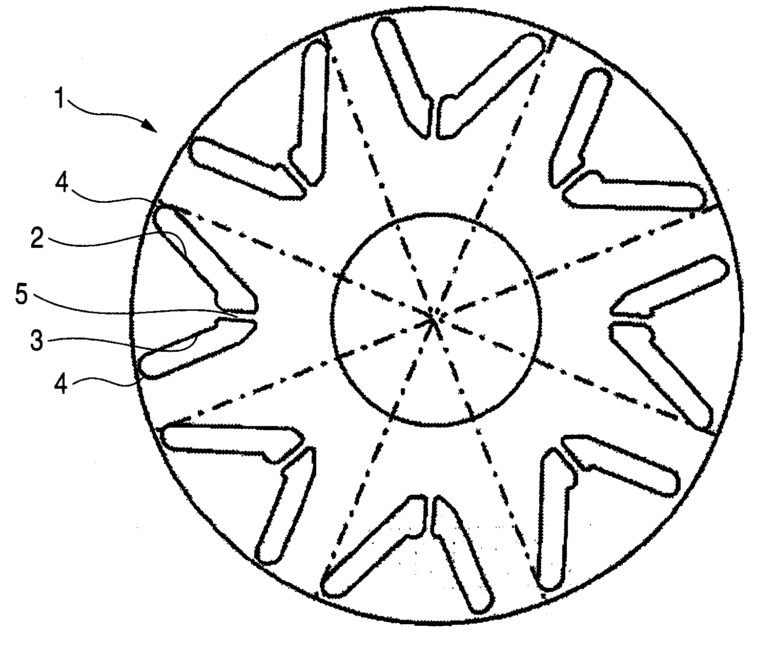
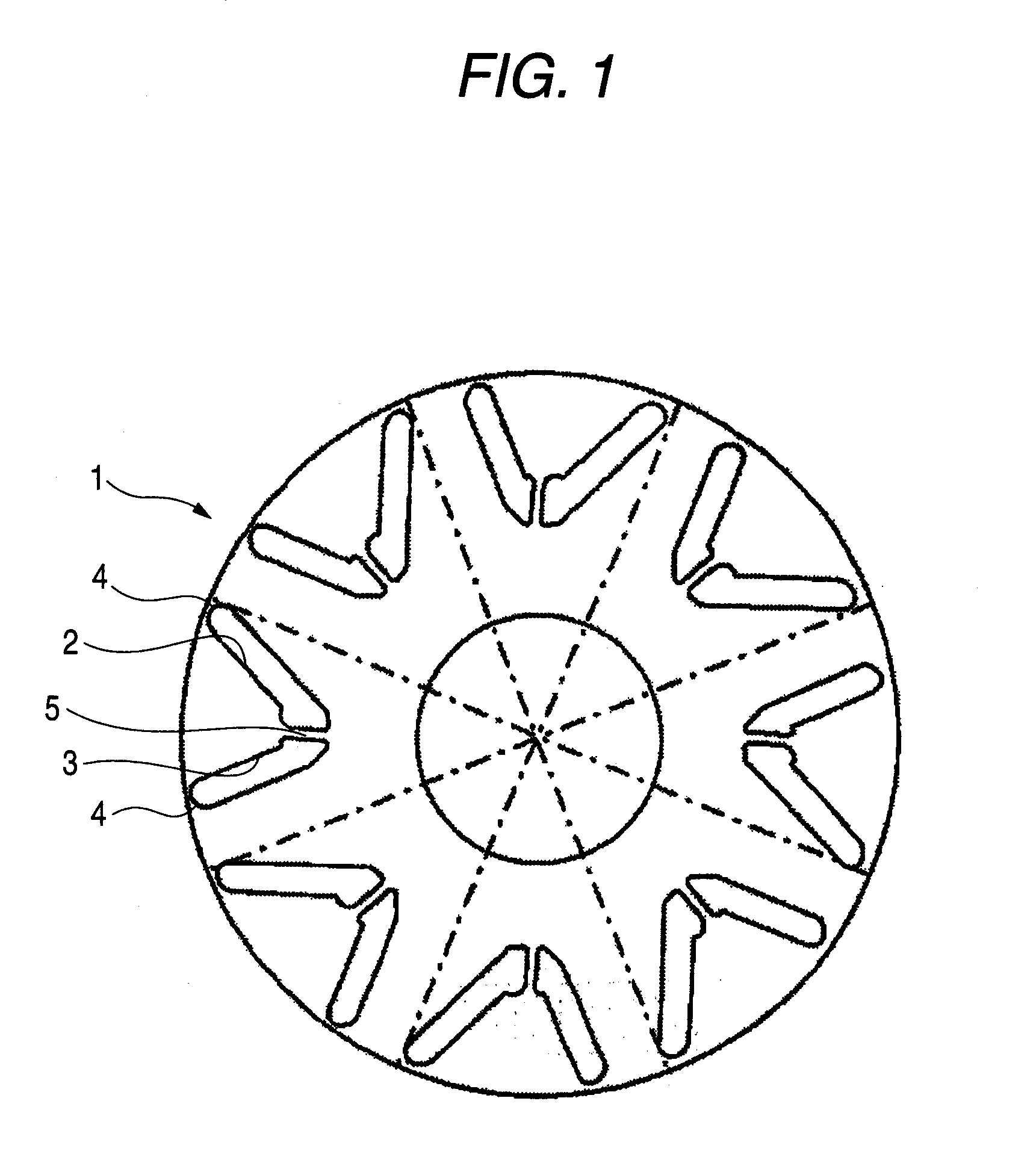
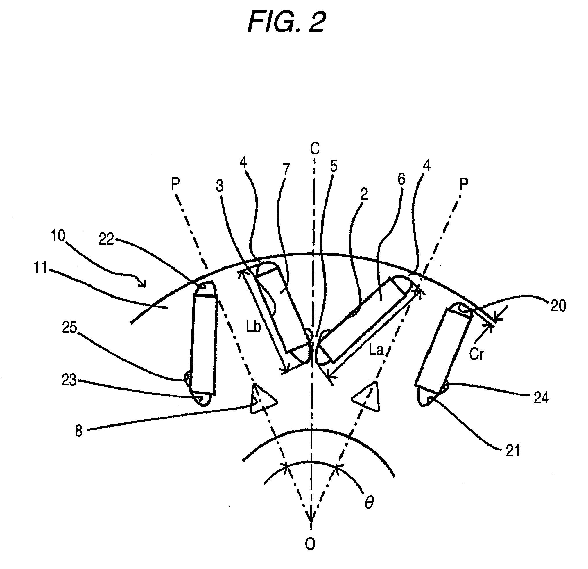
[0067]FIG. 1 is a front view of an electromagnetic steel plate forming member blanked in order to form a rotor core, which shows an embodiment of the invention, and FIG. 2 is an enlarged front sectional view of a rotor to which the electromagnetic steel plate forming member is applied, which shows a structure of the rotor.

[0068]In FIG. 1, reference numeral 1 is an electromagnetic steel plate forming member, 2 and 3 are first and second magnet holes, and 4 is an outer bridge. Further, in FIG. 2, reference numeral 5 is a center bridge, 6 and 7 are first and second permanent magnets, 8 is a cavity portion, 10 is a rotor, 11 is a rotor core, and 20, 21, 22, 23, 24, and 25 are arcuate spaces for preventing flux leakage. Reference character O is a center of rotation, OP is a pole pitch line, OC is a center line of the pole pitch lines, θ is a pole pitch angle, La and Lb are respectively lengths in a radius direction of the first and second magnet holes 2 and 3, and Cr is a distance of an ...


PUM


Abstract

An electromagnetic steel plate forming member provides the two magnet holes for inserting therein the two permanent magnets per pole along the V-shape, which are provided in the region of the radial pole pitch lines OP provided in the rotor core at the predetermined pole pitch angle θ, one magnet hole is displaced in a direction apart from the center line OC of the pole pitch lines OP, and the other magnet hole is displaced in a direction approaching to the center line OC of the pole pitch lines OP.

Description

[0001]The present invention claims priority from Japanese Patent Application No. 2007-072140 filed on Mar. 20, 2007, the entire content of which is incorporated herein by reference.BACKGROUND OF INVENTION[0002]1. Field of the Invention[0003]The present invention relates to an electromagnetic steel plate forming member, an electromagnetic steel plate laminator, a permanent magnet type synchronous rotating electric machine rotor provided with this laminator, a permanent magnet type synchronous rotating electric machine, and a vehicle, an elevator, a fluid machine, and a processing machine using the rotating electric machine. These are used as a drive motor or a generator for a vehicle such as a hybrid car, a fuel cell car or an electric car; or as a drive motor or a generator for an industrial power saving machine such as a crane, a winding machine, an elevator, an elevator in a multi-level parking zone, a compressor or a blower for wind or water power, a fluid machine such as a pump,...

Claims


Application Information

Patent Timeline
Patent Type & Authority Applications(United States)
IPC IPC(8): H02K1/27H02K1/28H02K21/00
CPCH02K1/2766H02K2213/03H02K21/14H02K1/06H02K1/22
Inventor SUZUKI, TAKEOMAEMURA, AKIHIKOKAWAZOE, YOSUKEFUKUMA, YUTOINOUE, TAKESHI
Owner YASKAWA DENKI KK
Why Eureka
Try Eureka