Image Forming Apparatus Appropriately Setting Current Value for Driving Motor

Inactive Publication Date: 2008-09-25
KONICA MINOLTA BUSINESS TECH INC
View PDF4 Cites 16 Cited by
  • Summary
  • Abstract
  • Description
  • Claims
  • Application Information

AI Technical Summary

Benefits of technology

[0018]The present invention has been made in view of these problems. It is one of the objects of the present invention that, in an image forming apparatus in which a stepping motor, driving of which is controlled in a constant-current system, is mounted, a current that causes an optimu

Problems solved by technology

During such a time, the stepping motor operates with the current setting that causes excessive motor output with respect to the load torque required.
If the motor output is excessive with respect to the load, surplus energy is produced in addition to the required energy.
The surplus energy increases the vibration of the stepping motor.
As a result, there arises a problem that the noise generated when the image forming apparatus is dr

Method used


Image

  • Image Forming Apparatus Appropriately Setting Current Value for Driving Motor
  • Image Forming Apparatus Appropriately Setting Current Value for Driving Motor
  • Image Forming Apparatus Appropriately Setting Current Value for Driving Motor

Examples


first embodiment

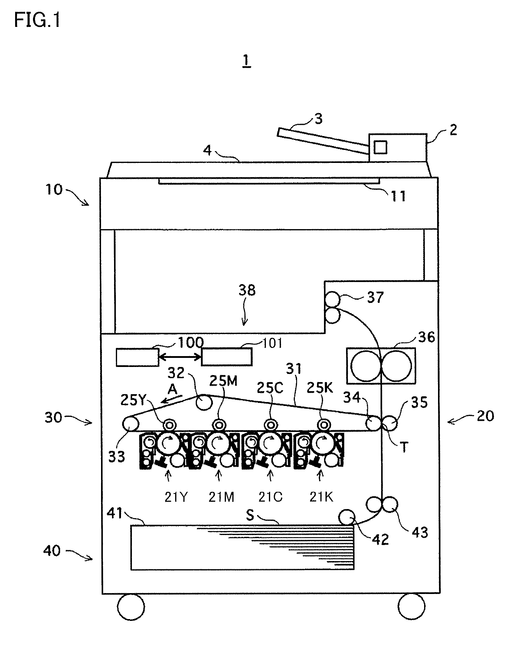
[0048]In a first embodiment, description is given on a case where an image forming apparatus according to the present invention is applied as a digital color copier (hereinafter referred to as a “copier”) of a tandem system. However, the image forming apparatus according to the present invention is not limited to copiers. The image forming apparatus according to the present invention may be a printer, a facsimile machine, or an MFP, which is a multifunctional machine having functions of these machines, as long as they are image forming apparatuses using a stepping motor for a drive mechanism. The printing system is not limited to the tandem system, and further is not limited to the digital system. Moreover, the apparatus may be a monochrome machine instead of the color machine.

[0049]An image forming apparatus of a color tandem system is configured such that four color image forming parts each including a developer aligned along an intermediate transfer belt. The intermediate transfe...

second embodiment

[0125]FIG. 13 schematically shows a longitudinal section of a copier 1, which is a second embodiment of the image forming apparatus of the present invention Copier 1 according to the present second embodiment has the same hardware configuration as that of copier 1 according to the first embodiment shown in FIG. 1.

[0126]Image forming parts 21Y, 21M, 21C, and 21K of copier 1 according to the second embodiment are configured to be attached with cartridges that contain toners, each of which corresponds to each color, although not described in connection with FIG. 1.

[0127]Specifically, in the second embodiment, with reference to FIG. 13, a stepping motor M1 refers to one specific example of a stepping motor for use in a fixing driver, a stepping motor M2 to one specific example of a stepping motor for use in a PC (Photo Conductor) driver, and a stepping motor M3 to one specific example of a stepping motor for use in a toner supply driver. The representative of stepping motors M1 to M3 is...

third embodiment

[0156]FIG. 18 schematically shows a longitudinal section of a color printer 200, which is a third embodiment of the image forming apparatus of the present invention.

[0157]Color printer 200 includes a controller 201 that performs overall control over the operations of color printer 200, a memory 202 that stores programs that controller 201 executes and various data, and a display 203. The display content of display 203 is controlled by controller 201.

[0158]Color printer 200 is mainly constituted of a photosensitive unit including a photoconductor drum 227 and a charger 212, a developing unit including a developing rack 99, an intermediate transfer unit including an intermediate transfer belt 221, a laser scanning unit including an exposure machine 240, and a fixing unit including a fixing device 244.

[0159]In the photosensitive unit, photoconductor drum 227 is charged by charger 212 and is rotated in the direction of an arrow X in FIG. 18 by a driving device (not shown).

[0160]Developi...


PUM


Abstract

When a printing instruction is provided, a CPU causes a stepping motor M to drive a developer and calculates the value of a load of the stepping motor M before printing operations are performed. Then, CPU determines whether the value of the load is within a predetermined range stored in advance. If the value is not within the predetermined range, CPU causes a display to display an error message.

Description

[0001]This application is based on Japanese Patent Applications Nos. 2007-074476 and 2007-093596 filed with the Japan Patent Office on Mar. 22, 2007 and on Mar. 30, 2007, respectively, the entire content of which is hereby incorporated by reference.BACKGROUND OF THE INVENTION[0002]1. Field of the Invention[0003]The present invention relates to an image forming apparatus, and particularly to an image forming apparatus using a stepping motor for a drive mechanism.[0004]2. Description of Related Art[0005]In image forming apparatuses such as copiers, printers, and multifunction peripherals (MFPs), a stepping motor is used as the drive source, in some cases. In such image forming apparatuses, a constant-current drive system (hereinafter referred to as a “constant-current system”) is employed as a system for controlling a stepping motor in many instances. In the constant-current system, at the start of driving, a relatively high voltage is applied to a stepping motor until a target curren...

Claims


Application Information

Patent Timeline
IPC IPC(8): H02P8/38H02P8/12
CPCG03G15/06G03G15/502H02P8/14G03G15/5008
Inventor TSUJIMOTO, TAKAHIROSAKAI, KATSUHIDEOHARA, KOUJIYABUKI, SHINICHI
Owner KONICA MINOLTA BUSINESS TECH INC
Why Eureka
Try Eureka