Dual-band f-slot patch antenna

a patch antenna and dual-band technology, applied in the field of multi-band antennas, can solve the problems of increasing the size of the antenna, unattractive designs for modern handheld communication devices, and very limited bandwidth of the antenna, so as to reduce the difficulty of design and fabrication and improve the matching

Active Publication Date: 2008-09-25
MALIKIE INNOVATIONS LTD
View PDF1 Cites 25 Cited by
  • Summary
  • Abstract
  • Description
  • Claims
  • Application Information

AI Technical Summary

Benefits of technology

[0011]As will become apparent, the dual-band antenna is suitable for WLAN 2.45 GHz and 5 GHz applications. Further, the structure of the dual-band antenna has reduced design and fabrication difficulty in comparison to conventional dual-band antennas, and allows the frequencies of the upper and lower bands to be adjusted independently of one another, with improved impedance matching.

Problems solved by technology

Patch antennas are common in wireless handheld communication devices due to their low profile structure.
However, since conventional PIFA antennas have a very limited bandwidth, broadband technologies, such as parasitic elements and / or multi-layer structures, have been used to modify the conventional PIFA antenna for multi-band and broadband applications.
These approaches increase the size of the antenna, making the resulting designs unattractive for modern handheld communication devices.
Also, the additional resonant branches introduced by these approaches make the operational frequencies of the antennas difficult to tune.
Further, the additional branches can introduce significant electromagnetic compatibility (EMC) and electromagnetic interference (EMI) problems.

Method used


Image

  • Dual-band f-slot patch antenna
  • Dual-band f-slot patch antenna
  • Dual-band f-slot patch antenna

Examples


Embodiment Construction

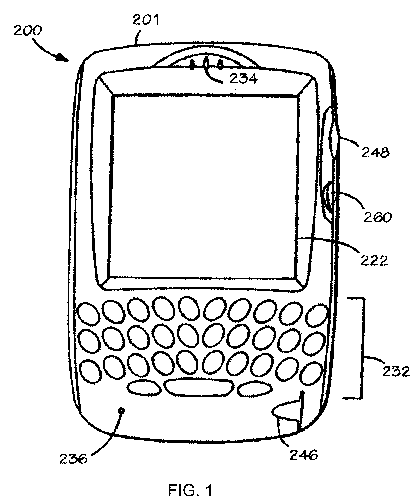
[0018]Turning to FIG. 1, there is shown a sample handheld communications device 200 in accordance with the invention. Preferably, the handheld communications device 200 is a two-way wireless communications device having at least voice and data communication capabilities, and is configured to operate within a wireless cellular network. Depending on the exact functionality provided, the wireless handheld communications device 200 may be referred to as a data messaging device, a two-way pager, a wireless e-mail device, a cellular telephone with data messaging capabilities, a wireless Internet appliance, or a data communication device, as examples.

[0019]As shown, the handheld communications device 200 includes a display 222, a function key 246, and data processing means (not shown) disposed within a common housing 201. The display 222 comprises a backlit LCD display. The data processing means is in communication with the display 222 and the function key 246. In one implementation, the b...


PUM


Abstract

A dual-band antenna includes a planar conductive layer comprising a conductive region and a central non-conductive region. The conductive region and the non-conductive region together define a pair of interconnected F-slot structures, and a loop strip structure coupled to and disposed around the F-slot patch slot antenna structures.

Description

FIELD OF THE INVENTION[0001]The invention described herein relates to a multi-band antenna for a handheld wireless communications device. In particular, the invention relates to a dual-band patch antenna.BACKGROUND OF THE INVENTION[0002]Patch antennas are common in wireless handheld communication devices due to their low profile structure. Further, patch antennas can be implemented with a virtually unlimited number of shapes, thereby allowing such antennas to conform to most surface profiles. Since modern handheld communication devices are required to operate in multiple frequency bands, multi-band patch antennas have been developed for use in such devices.[0003]For instance, Wen (U.S. Pat. No. 7,023,387) describes a dual-band antenna that comprises a first C-shaped patch antenna structure, and a second C-shaped patch antenna structure coupled to the first patch antenna structure, each patch antenna structure having a respective slot structure. The first patch antenna structure incl...

Claims


Application Information

Patent Timeline
Patent Type & Authority Applications(United States)
IPC IPC(8): H01Q13/10
CPCH01Q9/0407H01Q5/371H01Q5/357H01Q13/10
Inventor RAO, QINJIANGWEN, GEYIWANG, DONGPECEN, MARK
Owner MALIKIE INNOVATIONS LTD
Why Eureka
Try Eureka