

Back pressure adjustment apparatus for liquid ejection head
- Summary
- Abstract
- Description
- Claims
- Application Information
AI Technical Summary
Benefits of technology
Problems solved by technology
Method used
Image

Examples
Embodiment Construction
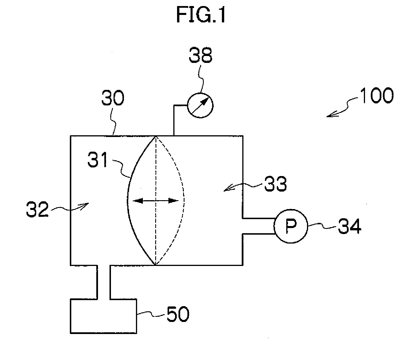
[0046]FIG. 1 is a schematic drawing showing the basic composition of a back pressure adjustment apparatus 100 relating to an embodiment of the present invention.
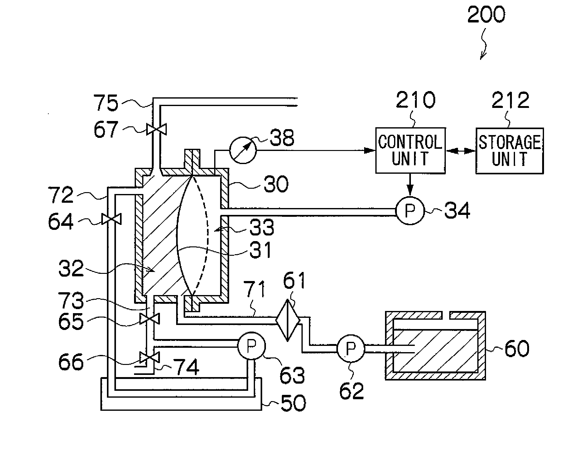
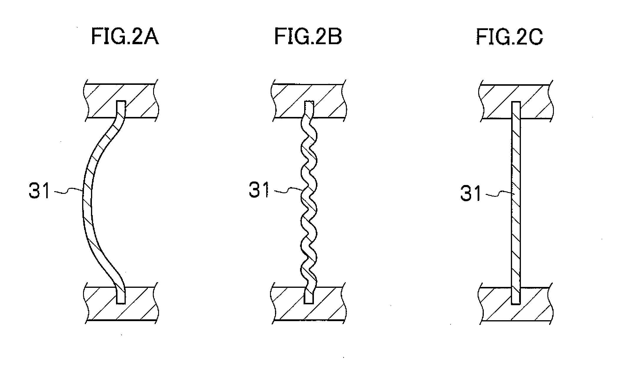
[0047]In FIG. 1, a rigid container 30 is divided into a liquid accommodating chamber 32 and a gas accommodating chamber 33 by means of one movable film 31 which is deformable. In other words, the movable film 31 constitutes a barrier which demarcates the rigid container 30 into a liquid accommodating chamber 32 and a gas accommodating chamber 33, and the movable film 31 constitutes a portion of the whole side wall of the liquid accommodating chamber 32, as well as constituting a portion of the whole side wall of the gas accommodating chamber 33.
[0048]The liquid accommodating chamber 32 is a chamber which is connected to a liquid ejection head 50, which forms a liquid ejection device for ejecting a prescribed liquid, such as ink, onto a prescribed ejection receiving medium. The liquid accommodating chamber 32 temporarily acco...
PUM
 Abstract
Description
Claims
Application Information