Automated compliance testing for video devices

Active Publication Date: 2008-09-25
ATI TECH INC
View PDF6 Cites 69 Cited by
  • Summary
  • Abstract
  • Description
  • Claims
  • Application Information

AI Technical Summary

Problems solved by technology

At relatively high data rates, achieving the required BER may present multiple design challenges.
Typically, all this is done manually, and is

Method used


Image

  • Automated compliance testing for video devices
  • Automated compliance testing for video devices
  • Automated compliance testing for video devices

Examples


Embodiment Construction

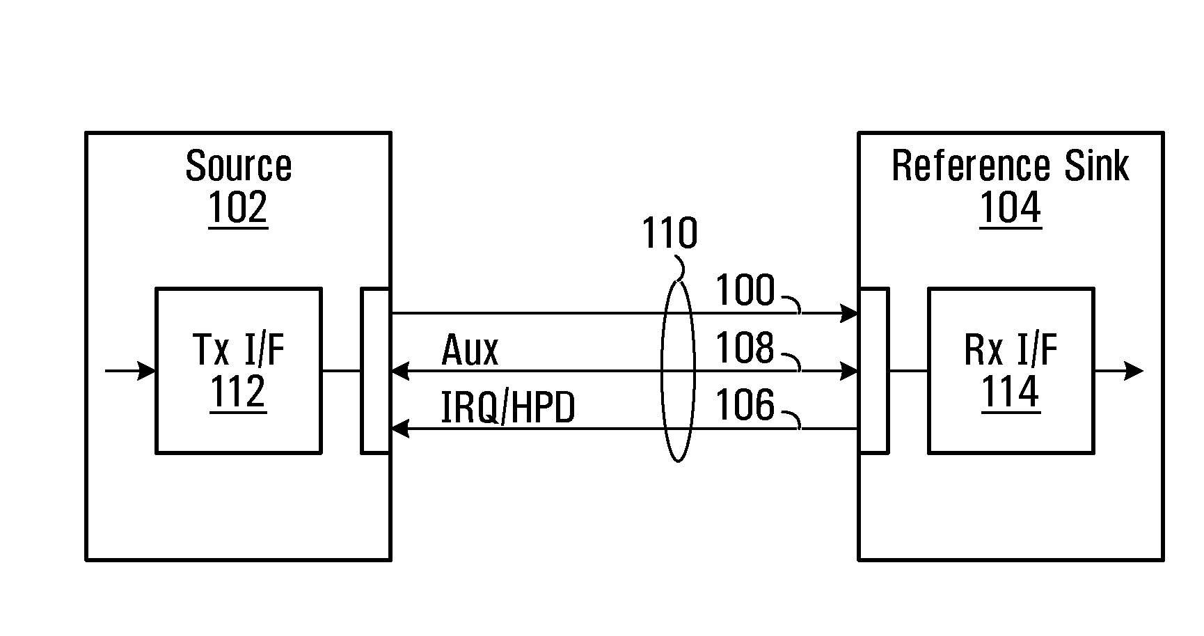
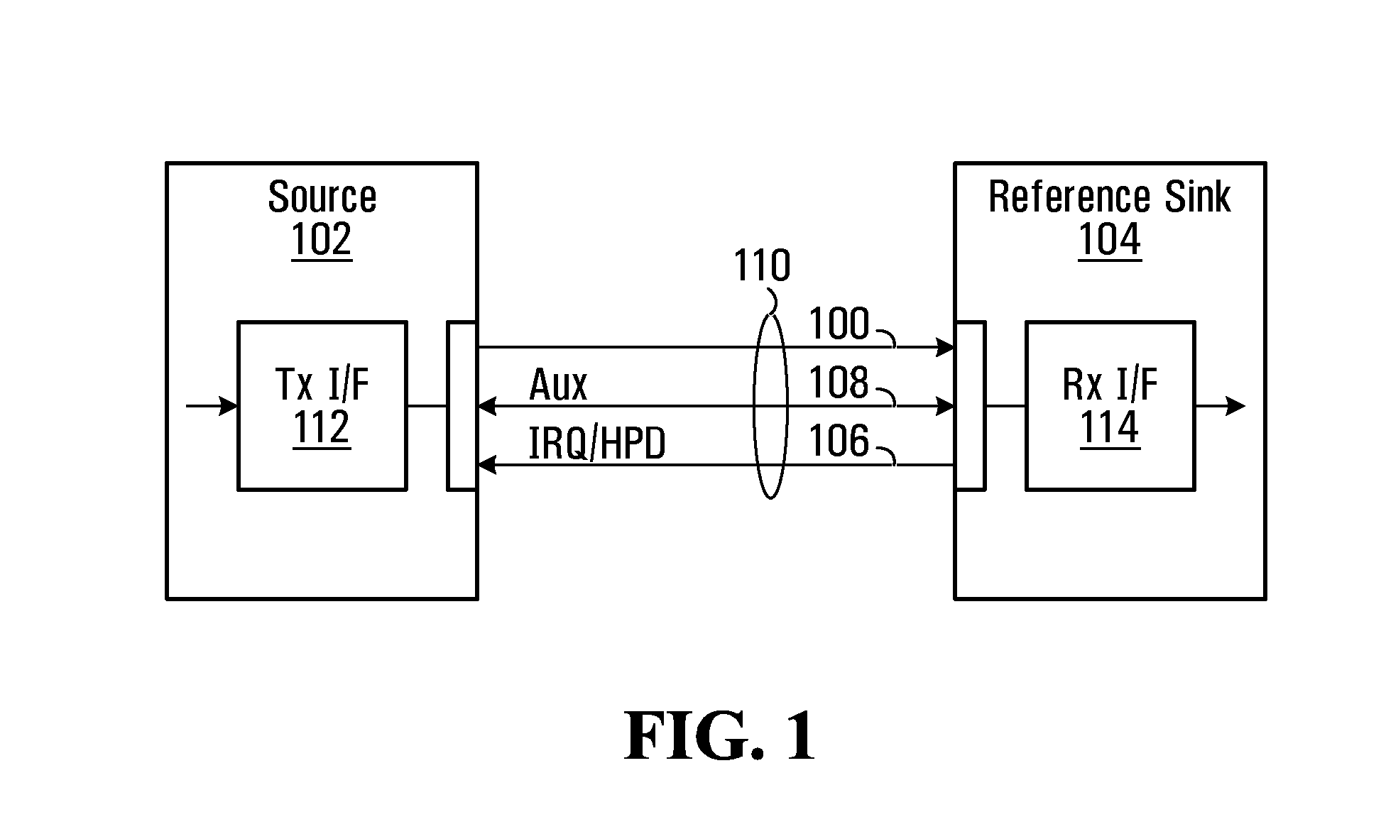
[0031]FIG. 1 is a simplified schematic block diagram of a digital video transmitter / receiver pair including a video source 102 and a video sink 104 interconnected by a serial link. As illustrated, a physical link 110 carries a main forward transmission channel 100 that may be used to send data from source 102 to sink 104, and a bi-directional auxiliary channel 108 that may be used by both source 102 and sink 104 to communicate status and control data between them. Link 110 may further carry an interrupt request (IRQ) line 106, to signal interrupts from sink 104 to source 102. Link 110 is suitable for the exchange of video and audio, and may for example be a DisplayPort compliant link. Link 110 may be interconnected between devices using a single physical connector at source 102 and sink 104, emanating at a port at source 102 and terminating at a port at sink 104. A transmit interface 112 formats data from a video, audio, or other multimedia data source for transmission over link 110...


PUM


Abstract

A method of automated video device testing, and source and sink video devices are disclosed. A test signal may be provided by way of a video link from a video source to a video sink, over a video link extending therebetween. The method includes receiving on the video link a request from the video sink to provide the test signal; identifying based on the request, a requested test signal; providing the requested test signal from the video source to the video sink over the video link. In another embodiment, a video sink may be queried over a video link to determine a metric describing at least a portion of know video signal, as received and determined at the video sink to verify integrity of the video signal at the video sink.

Description

CROSS-REFERENCE TO RELATED APPLICATIONS[0001]This application claims benefits from U.S. Provisional Patent Application No. 60 / 895,645 filed Mar. 19, 2007, the contents of which are hereby incorporated herein by reference.FIELD OF THE INVENTION[0002]The present invention relates generally to digital video devices, and more particularly to methods of automating certain test procedures that may be used to assess whether video devices perform as expected.BACKGROUND OF THE INVENTION[0003]Digital processing and presentation of information is now in wide spread use in the consumer electronics and personal computing industries. Video, audio and text are now digitally manipulated and presented in a variety of applications.[0004]In particular, digital display terminals are fast becoming commonplace—rapidly replacing older analog devices such as cathode ray tube displays. Digital video transmission may take place between two integrated circuits in a given display device or between two external...

Claims


Application Information

Patent Timeline
IPC IPC(8): H04N17/00
CPCG09G3/006G09G3/2096H04N17/04G09G2370/04G09G5/006
Inventor GLEN, DAVIDLUK, BETTY
Owner ATI TECH INC
Why Eureka
Try Eureka