Frictional Pivots for Gravitational Alignment

Inactive Publication Date: 2008-09-25
BLACK & DECKER INC
View PDF2 Cites 0 Cited by
  • Summary
  • Abstract
  • Description
  • Claims
  • Application Information

AI Technical Summary

Benefits of technology

[0011]Pendulous movement is resisted by the frictional force in the pivot, thus preventing free oscillations of the pendulous components, but the pivot is not so frictional as to inhibit the pendulous components from coarsely aligning with gravity.
[0012]Vibration is applied to one or more members of the pivot. This vibration causes one element of the pivot to move fractionally relative to the other. This converts the static friction into dynamic friction. Thus, for the duration of the pulse of vibration, further movement is enabled and the pendulous components, under the influence of the gravitational restoring force, move closer to gravitational alignment. So that the momentum of the pendulous components does not cause them to move past the point of gravitational alignment, the pulses of vibration should be shorter than a quarter of the period of the pendulum. The vibration of the pendulum therefore ceases around the position of gravitational alignment and the comparatively high static friction in the un-vibrated pivot will reduce the extent of the motion b

Problems solved by technology

With a high-friction pivot this accuracy will be poor.
With a low-friction pivot, the accuracy of alignment will be better, but the lower

Method used


Image

  • Frictional Pivots for Gravitational Alignment
  • Frictional Pivots for Gravitational Alignment
  • Frictional Pivots for Gravitational Alignment

Examples


Example

[0025]In all of the drawings, switching / timing means and portable power means have been omitted for clarity.

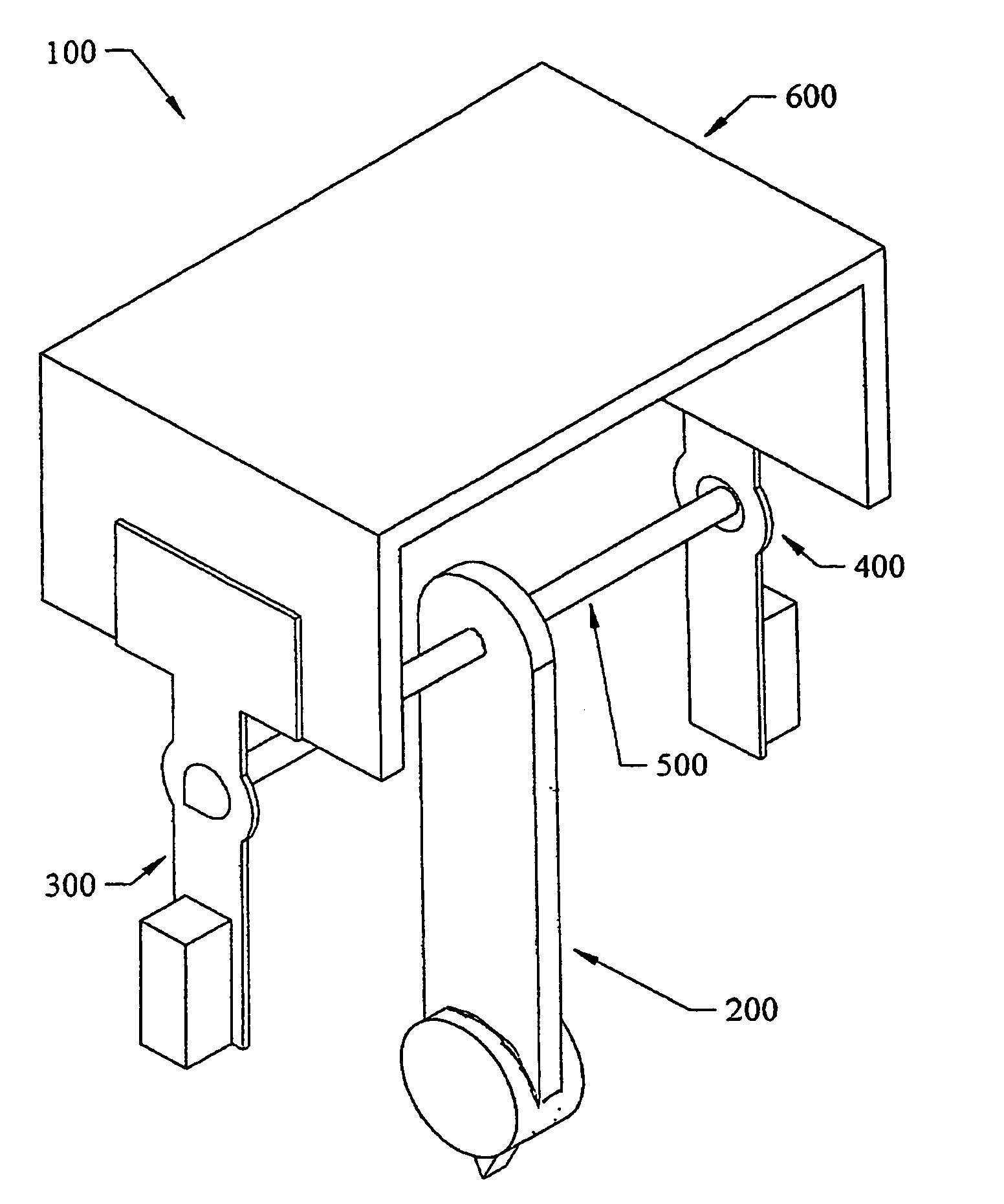
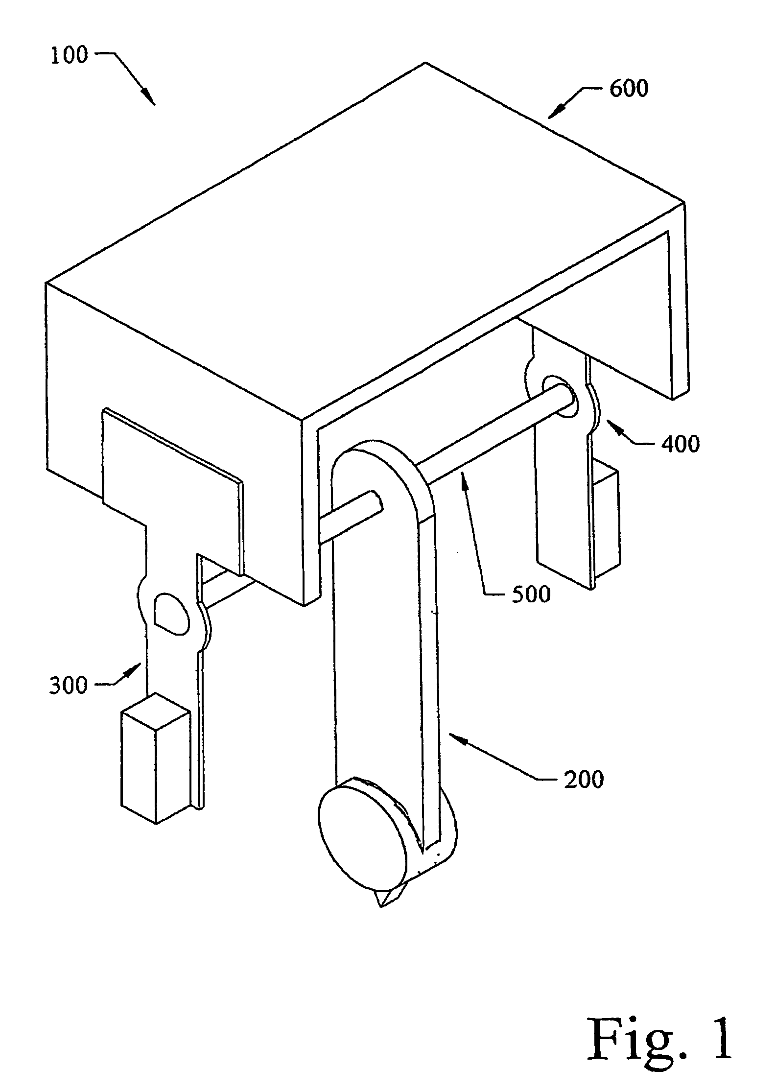
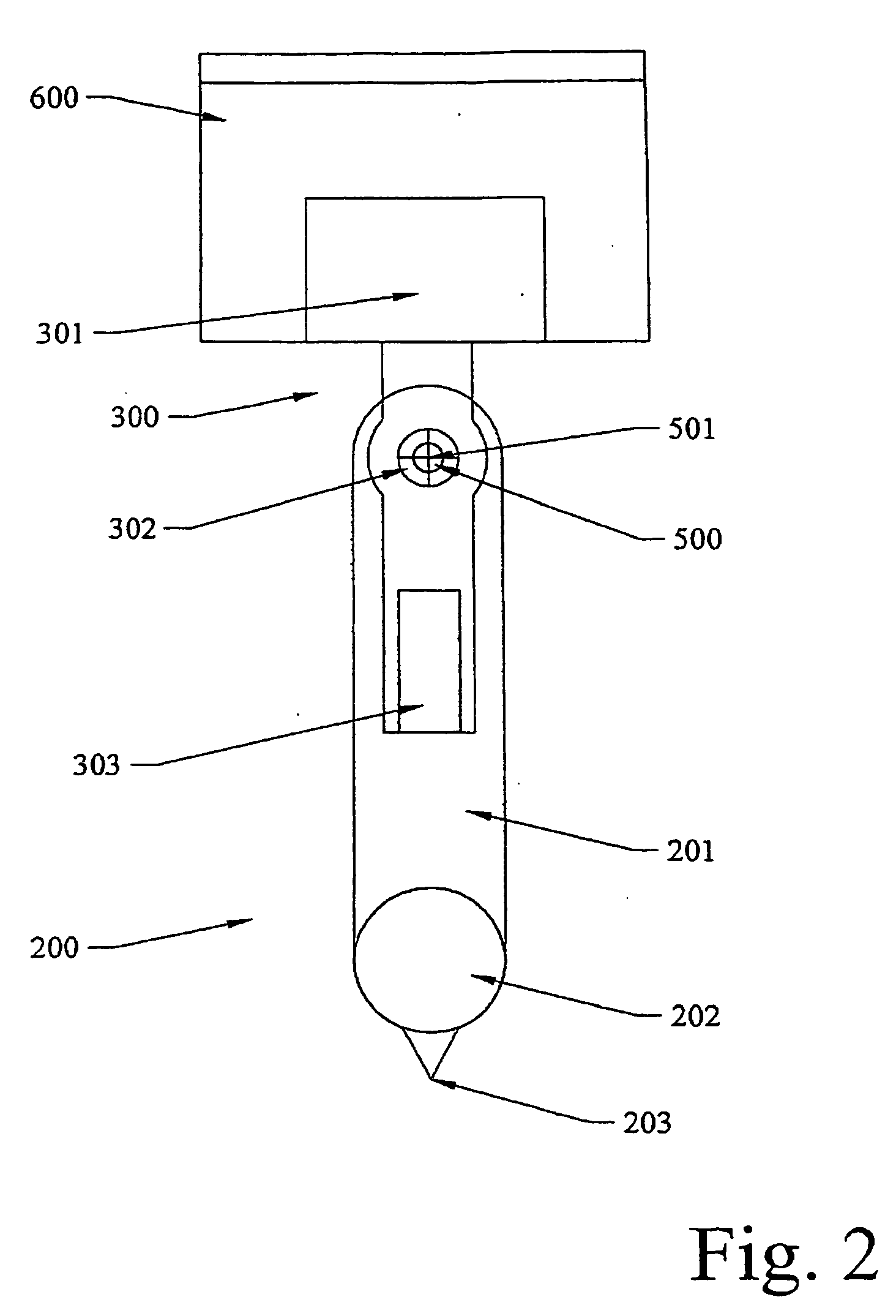
[0026]FIGS. 1 to 4 show a frictional pivot 100 comprising a pendulous assembly 200 connected via axial shaft 500 to pivot halves 300 and 400 which are rigidly attached to case 600.

[0027]The pendulous assembly 200 includes a pendulum 201, weight 202 and reference point 203. Pivot half 300 is a plate 301 with a conical depression 302 and vibrating means 303. Plate 301 is rigidly attached to case 600 in such a way that an elongate portion comprising the conical depression 302 and the vibrating means 303 is able to move axially with reference to shaft 500. This movement is governed by the gauge and springiness of plate 301. Similarly pivot half 400 comprises plate 401 with a conical depression 402 and vibrating means 403. Axial shaft 500 has conical ends 501 and 502 which locate in conical depressions 302 and 402. The relative angles of shaft end and depression may be such that on...


PUM


Abstract

A frictional pivot 100 for use in a device measuring gravitational alignment is provided. The frictional pivot 100 comprises a gravity-responsive directional means 200 for indicating a datum direction of alignment with gravity; frictional pivoting means 300, 400 for allowing the gravity-responsive means coarsely to align with gravity; vibration means 303, 403 for vibrating one or more elements of the pivoting means; and portable power means 303a for powering the vibration means 303, 403.

Description

BACKGROUND OF THE INVENTION[0001]This invention relates to devices containing frictional pivots in general, and more particularly but not necessarily to devices such as laser levels, which rely on frictional pivots for gravitational alignment of pendulous components about an axis.[0002]The accuracy of such a device depends upon the accuracy with which the pendulous components align with gravity. Any misalignment leads to inaccuracy in the device. Friction in the point or points about which the pendulous components pivot is the chief cause of this misalignment. Conventionally, this problem is addressed by reducing friction in the pivot by employing such means as lubrication or precision roller bearings.[0003]Unfortunately, this conventional solution generates further problems, one of which is that as friction is reduced in the pivot, so the pendulous components take longer to stop oscillating and come to rest. As accurate readings cannot be taken until the pendulous components come t...

Claims


Application Information

Patent Timeline
IPC IPC(8): G01C9/12G01C15/00G01C15/10
CPCG01C15/105G01C15/008
Inventor WILLIAMS, NIGEL EMLYN
Owner BLACK & DECKER INC
Why Eureka
Try Eureka