End mill cutter

Active Publication Date: 2017-01-31
KENNAMETAL INC
View PDF56 Cites 0 Cited by
  • Summary
  • Abstract
  • Description
  • Claims
  • Application Information

AI Technical Summary

Benefits of technology

The invention is about improving the performance of end mill cutters by adding a sliding surface to the flanks of the cutting edge. This sliding surface helps to dampen the vibration of the workpiece, making it easier to control the cutting process. The region around the cutting edge is divided into a flank and a supporting surface, with the supporting surface acting as a reliable cutting edge and chip disposal. The supporting surface can be polished or coated with PVD thin films to prevent material accumulation and friction welds, ensuring a clean and smooth surface. Overall, this invention improves the efficiency and quality of end mill cutting operations.

Problems solved by technology

The sliding surface arranged in the region of the cutting edge comes into contact with the workpiece briefly after the engagement of the cutting edge, is supported on the workpiece and thus dampens again the unwanted vibratory movement of the workpiece.

Method used


Image

  • End mill cutter
  • End mill cutter
  • End mill cutter

Examples


Embodiment Construction

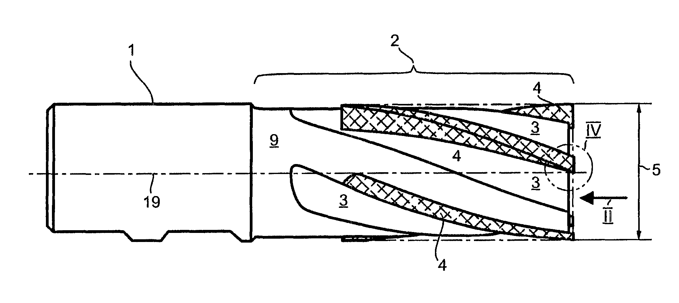
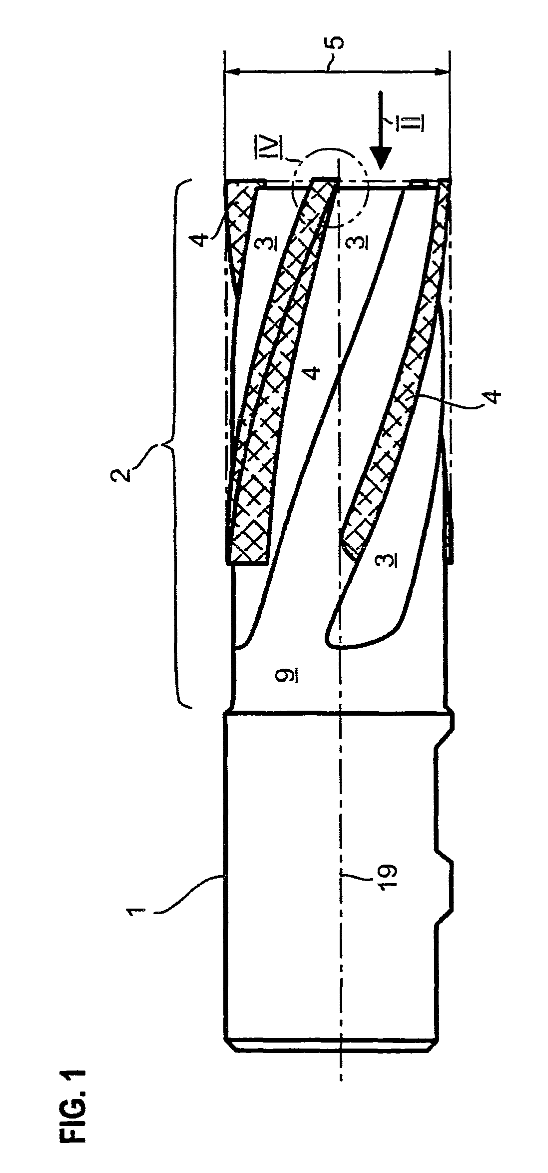
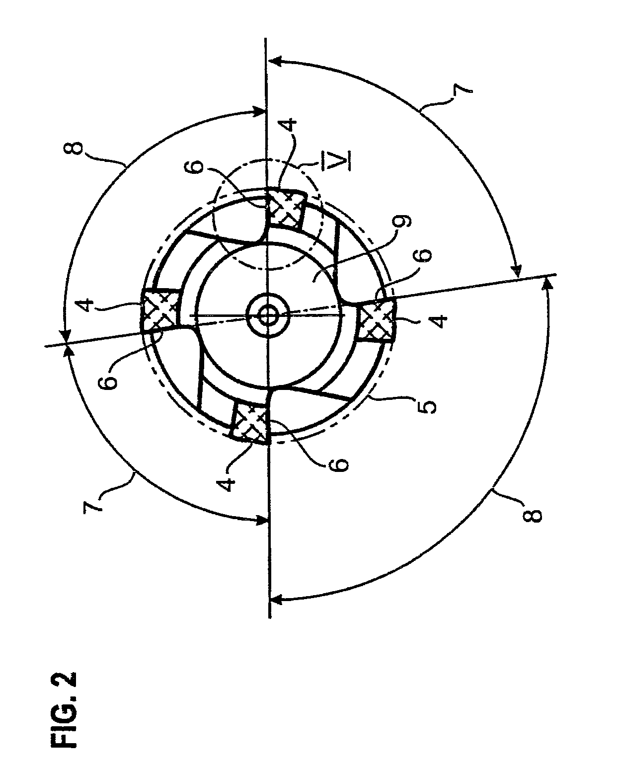
[0030]The end mill cutter shown in side view in FIG. 1 consists of a clamping shank 1 for clamping in a tool chuck and a cutter region 2. The helical flutes 3 and the brazed-on cutting edge modules 4 can be seen in the cutter region 2. The cutter outside diameter 5 in the region of the cutting edge 6 can also be seen. It can be seen from the plan view of FIG. 2 that the cutter shown in the exemplary embodiment is a four-edged end mill cutter having four cutting edge modules 4. The pitch of the cutting edge modules and thus of the cutting edges 6 relative to one another is unequal. A small pitch angle 7 and a large pitch angle 8 alternate with one another in each case. In the exemplary embodiment, the small pitch angle 7 is 83° in each case, whereas the large pitch angle 8 is 97° in each case.

[0031]The cutting edge modules 4, which are brazed-on carbide strips in the exemplary embodiment, are brazed onto a parent body 9 made of hot-work steel. The flank 11 adjoins the cutting edge 6 ...


PUM

PropertyMeasurementUnit
Diameteraaaaaaaaaa
Circumferenceaaaaaaaaaa

Abstract

End mill cutter having a plurality of cutting edges distributed over the circumference of the mill cutter, having a flank which is adjacent to the respective cutting edge in the circumferential direction and a supporting surface which adjoins the flank on that side which faces away from the cutting edge in the circumferential direction.

Description

BACKGROUND OF THE INVENTION[0001]Field of the Invention[0002]The invention relates to a multi-edged end mill cutter. Such end mill cutters are normally used as conventional-milling cutters for the rough and finish machining of workpieces. For the machining, the workpieces are not always clamped in chucks of special machine tools. On the contrary, it is also normal practice for workpieces suspended during production from special transport and conveying equipment to be machined by means of such end mill cutters. For example, it is normal practice in the production of automobiles to suspend axle carriers or similar subassemblies from simple stirrups and to then machine them.[0003]Description of the Related Art[0004]As a result of a lack of stable clamping in a workpiece chuck, the workpiece is suspended only in a very unstable manner, such that the milling tool rotating in the opposite direction causes the workpiece suspended in an unstable manner to vibrate during the milling. This vi...

Claims


Application Information

Patent Timeline
IPC IPC(8): B23C5/18B23C5/10
CPCB23C5/1081B23C2210/086B23C2210/282B23C2210/486B23C2210/56B23C2220/40B23C2222/28B23C2240/08B23C2250/16Y10T407/1908Y10T407/1948Y10T409/303752
Inventor HOBOHM, UWE
Owner KENNAMETAL INC
Why Eureka
Try Eureka