Opening and closing device

a technology of opening and closing, applied in the field of opening and closing devices, can solve the problems of time-consuming product process for attachment and assembly, and achieve the effects of preventing wobbling of the movable plate, simplifying the structure, and allowing diversification of operations

Inactive Publication Date: 2008-09-25
PANASONIC CORP
View PDF7 Cites 20 Cited by
  • Summary
  • Abstract
  • Description
  • Claims
  • Application Information

AI Technical Summary

Benefits of technology

[0010]The present invention offers an opening and closing device with a simple structure that allows diversifying operations.
[0011]In the opening and closing device of the present invention, a movable gear is movably or rotatably attached to a fixed plate or a movable plate movably disposed on a top face of the fixed plate. A fixed gear engaged with the movable gear is secured to one end of a spring member applying a force to the movable plate in a moving direction. This one end of the spring member is installed in an L-shaped guide hole provided on the movable plate, and another end of the spring member is attached to the movable plate. This simple structure achieves combined operations in an up-and-down direction and a right-and-left direction orthogonal to the up-and-down direction. The present invention thus offers the opening and closing device that allows diversifying operations.
[0012]Furthermore, the opening and closing device of the present invention includes multiple spring members and multiple guide holes. This prevents wobbling of the movable plate while moving the movable plate in the up-and-down direction and the right-and-left direction, ensuring reliable operations.

Problems solved by technology

Accordingly, a large number of components lead to a complicated structure, resulting in time-consuming product processes for attachment and assembly.

Method used


Image

  • Opening and closing device
  • Opening and closing device
  • Opening and closing device

Examples


first exemplary embodiment

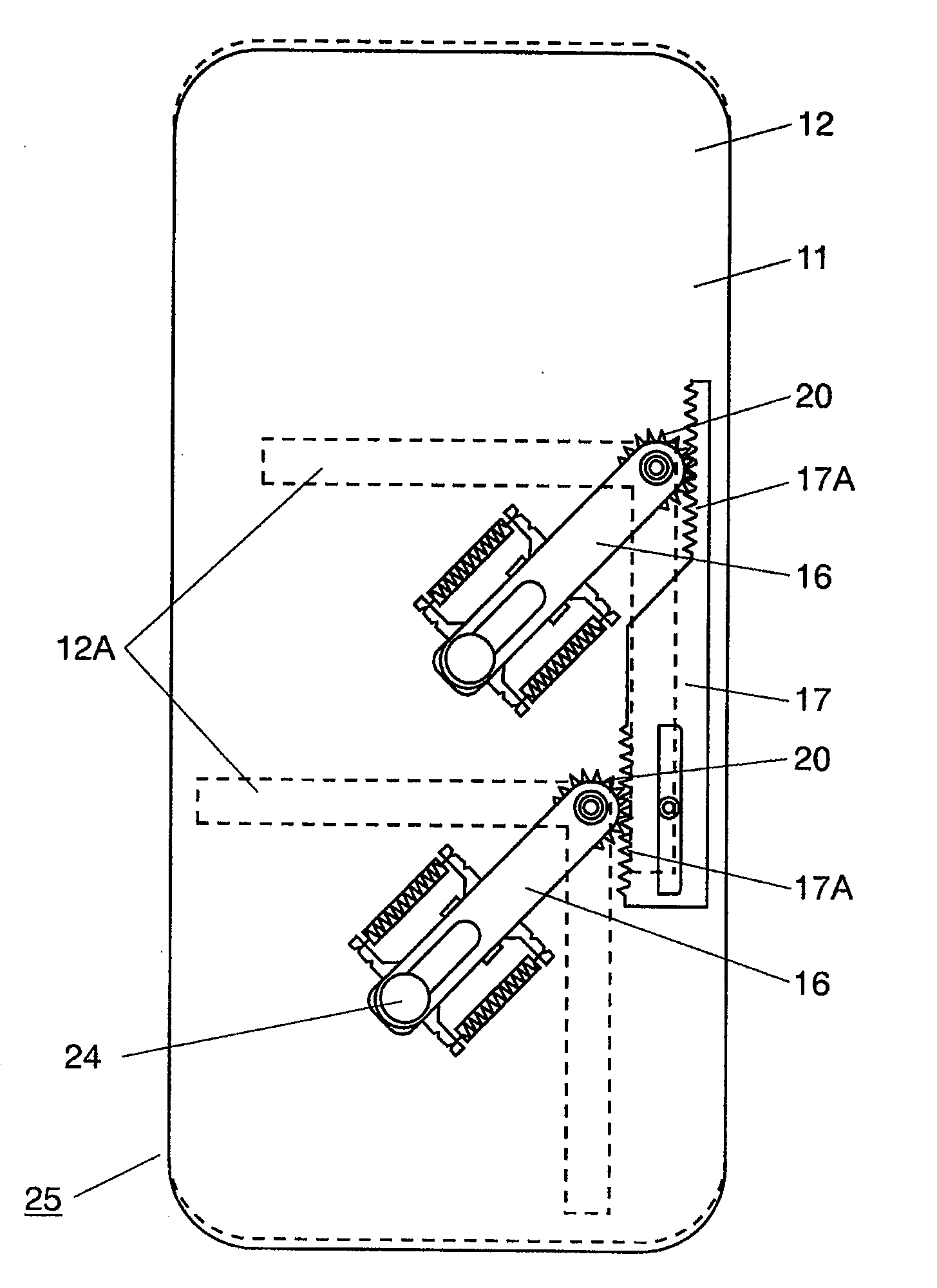
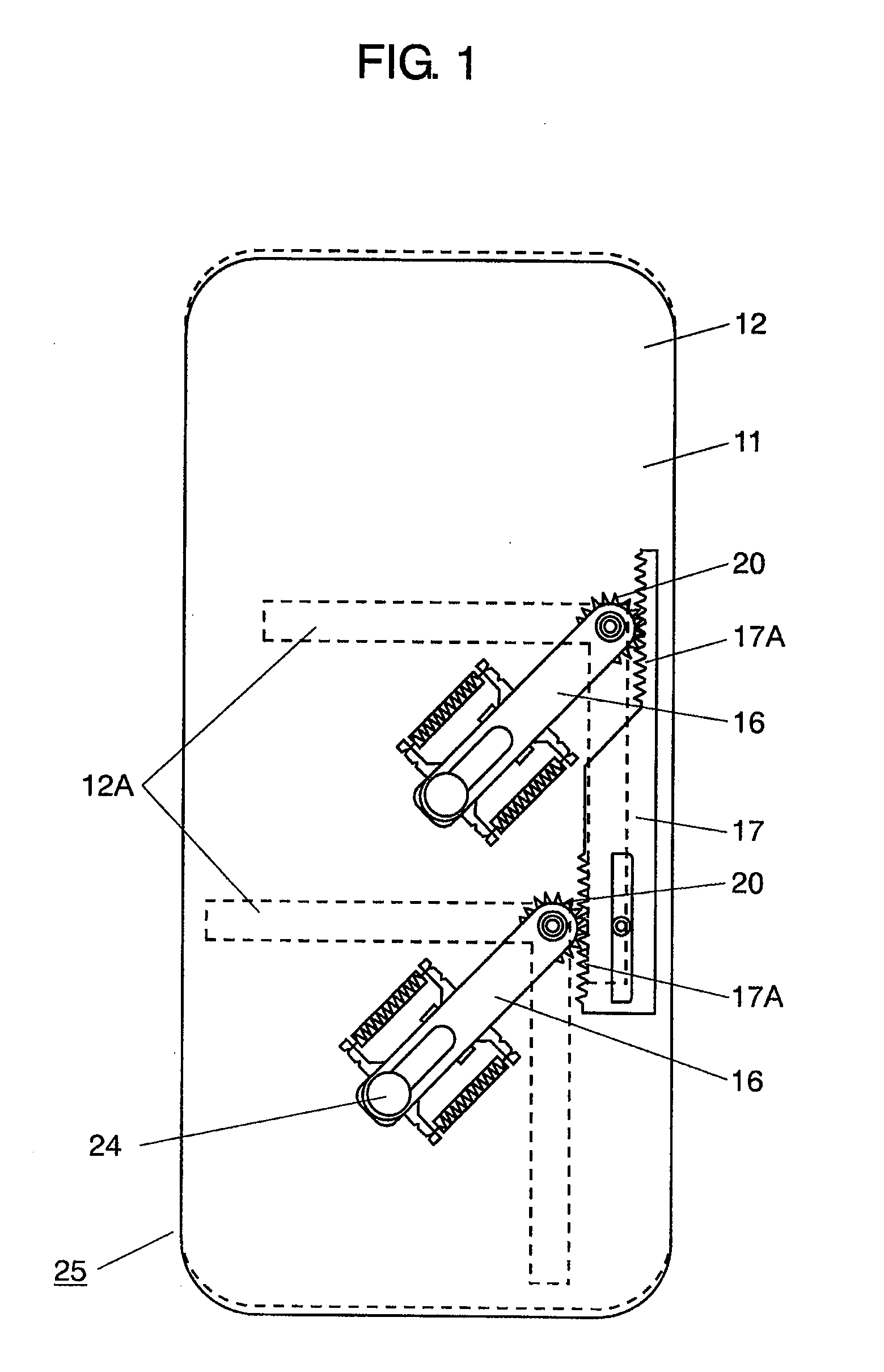
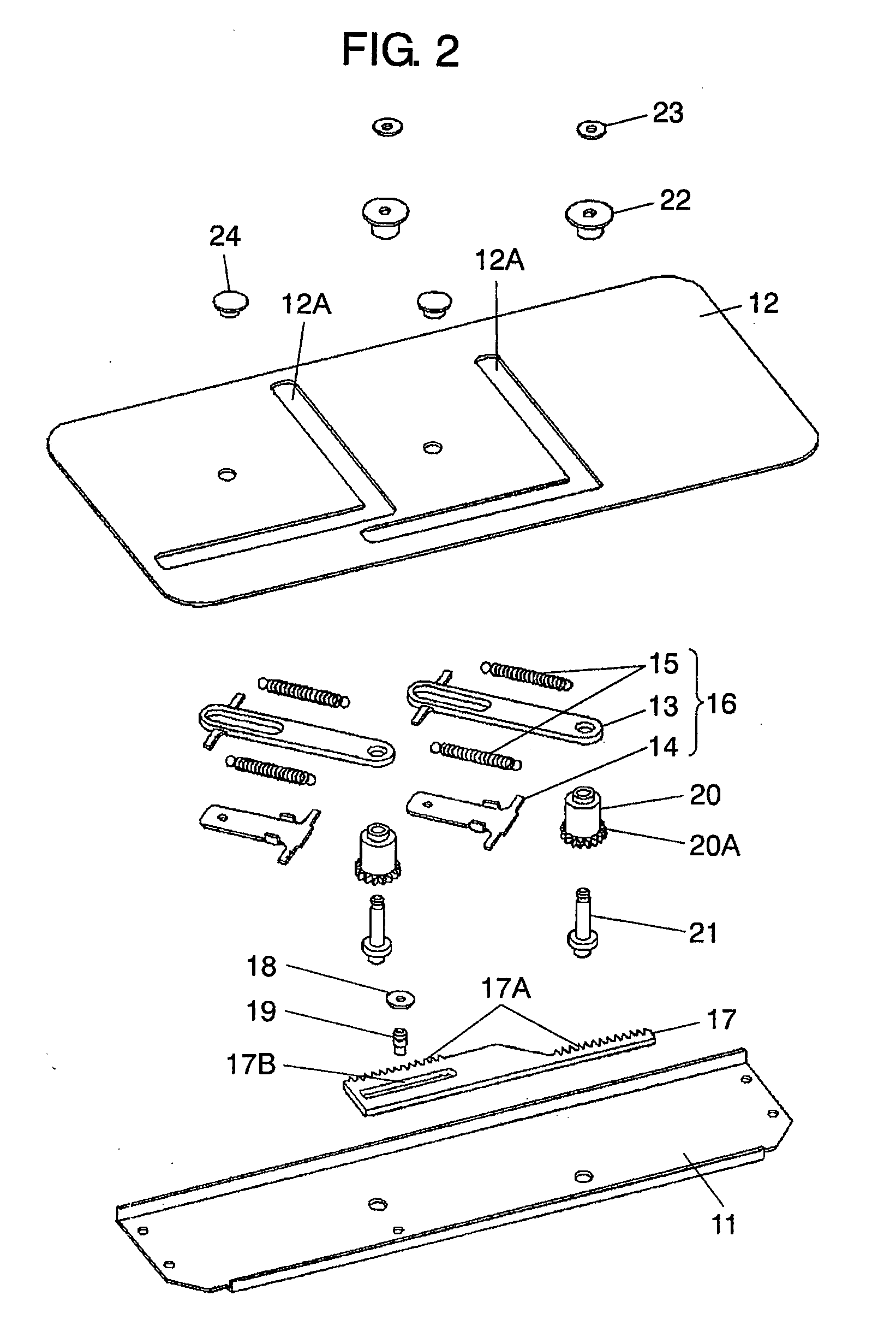
[0027]FIG. 1 is a plan view of an opening and closing device in the first exemplary embodiment of the present invention. FIG. 2 is an exploded perspective view of the opening and closing device in the first exemplary embodiment of the present invention. In FIGS. 1 and 2, fixed plate 11 is made of a sheet of metal, such as steel and copper alloy, or insulating resin. Movable plate 12 is disposed on a top face of fixed plate 11 in a movable manner in an up-and-down direction and a right-and-left direction orthogonal to the up-and-down direction. Movable plate 12 has two L-shaped guide holes 12A.

[0028]Upper frame 13 and lower frame 14 are made of a metal sheet or insulating resin. Spring 15 is made of a coiled steel wire or copper-alloy wire. On arms protruding from both side faces of upper frame 13 and lower frame 14, two slightly stretched springs 15 are hooked so that upper frame 13 and lower frame 14 pull each other to form spring member 16. In total, two spring members 16 are form...

second exemplary embodiment

[0044]FIG. 8 is a plan view of an opening and closing device in accordance with the second exemplary embodiment of the present invention. FIG. 9 is an exploded perspective view of the opening and closing device in the second exemplary embodiment of the present invention. The same reference names and marks are given to components same as that of the first exemplary embodiment to omit duplicate detailed description. In FIGS. 8 and 9, movable plate 42 is disposed on the top face of fixed plate 41 in a movable manner in an up-and-down direction and a right-and-left direction orthogonal to the up-and-down direction. Movable plate 42 has two L-shaped guide holes 42A. Plate-like upper frames 43 and lower frames 44 configure two spring members 46, respectively. In the second exemplary embodiment of the present invention, one spring 15 is fitted to a long hole in upper frame 43 and lower frame 144, and this slightly-stretched spring 15 establishes the state that upper frame 43 and lower fram...


PUM


Abstract

An opening and closing device in which a movable gear is movably disposed on a fixed plate, and a fixed gear engaged with the movable gear is secured to a right end of a spring member applying a force to a movable plate in a moving direction. This right end of the spring member is installed in an L-shaped guide hole and a left end of the spring member is attached to the movable plate. With this structure, the opening and closing device offers combined operations in an up-and-down direction and a right-and-left direction orthogonal to the up-and-down direction.

Description

BACKGROUND OF THE INVENTION[0001]1. Field of the Invention[0002]The present invention relates to opening and closing devices used in a range of electronic devices such as mobile phones and personal computers.[0003]2. Background Art[0004]With electronic devices such as mobile phones and personal computers becoming increasingly more diversified and sophisticated, many products are adopting designs that open and close a movable housing relative to a fixed housing so as to provide diversifying operations. Accordingly, more inexpensive and user-friendly opening and closing devices that allow diversifying operations are demanded for the use in these products.[0005]FIGS. 10A, 10B, and 10C are perspective views of a conventional mobile phone. As shown in FIG. 10C, operating part 2 including operation keys 2A and input keys 2B for inputting numbers and characters, and sound input part 3 such as a microphone are formed on the top face of fixed housing 1. Middle housing 4 is placed on the top ...

Claims


Application Information

Patent Timeline
Patent Type & Authority Applications(United States)
IPC IPC(8): H05K7/14
CPCH04M2250/18H04M1/0239
Inventor KUWAJIMA, HIDEKIKUDO, YASUCHIKA
Owner PANASONIC CORP
Why Eureka
Try Eureka