Loss-of-light detecting apparatus

a technology of loss-of-light and detection apparatus, which is applied in the direction of electromagnetic transmission, transmission monitoring, electromagnetic transceivers, etc., can solve the problems of inability of transponders to recognize and transponders cannot detect loss-of-ligh

Inactive Publication Date: 2008-09-25
FUJITSU LTD
View PDF3 Cites 19 Cited by
  • Summary
  • Abstract
  • Description
  • Claims
  • Application Information

AI Technical Summary

Benefits of technology

[0017]According to an aspect of an embodiment, an apparatus comprises: a correction level calculating unit that calculates a correction level, which is the input light level necessary to meet an optical signal-to-noise ratio at the maximum level of an optical noise signal; a loss-of-light detection threshold-value setting unit that compares the correction level with an initial threshold value to set a loss-of-light detection threshold value used in detection of any loss of light on the basis of the comparison result; and a loss-of-light detecting unit that compares the level of an input optical signal with the loss-of-light detection threshold value to determine that any loss of light is caused if the level of the input optical signal is lower than the loss-of-light detection threshold value, wherein the loss-of-light detection threshold-value setting unit sets the correction level as the loss-of-light detection threshold value if the correction level is higher than the initial threshold value and sets the initial threshold value as the loss-of-light detection threshold value if the correction level is lower than the initial threshold value.

Problems solved by technology

Since a channel CH1 has a sufficient input light power but the OSNR reference value of the channel CH1 is not met because the level of the ASE noise component is considerably higher than that of the main signal component, it is not possible for the transponder to recognize data through the channel CH1.
However, since it is determined whether the optical signal is received only on the basis of the input light power in the loss of light detecting function of transponders in related art, the transponders cannot detect any loss of light even if the loss of light is caused as in the channel CH1 and possibly erroneously recognize that the optical signal is normally received.

Method used


Image

  • Loss-of-light detecting apparatus
  • Loss-of-light detecting apparatus
  • Loss-of-light detecting apparatus

Examples


first embodiment

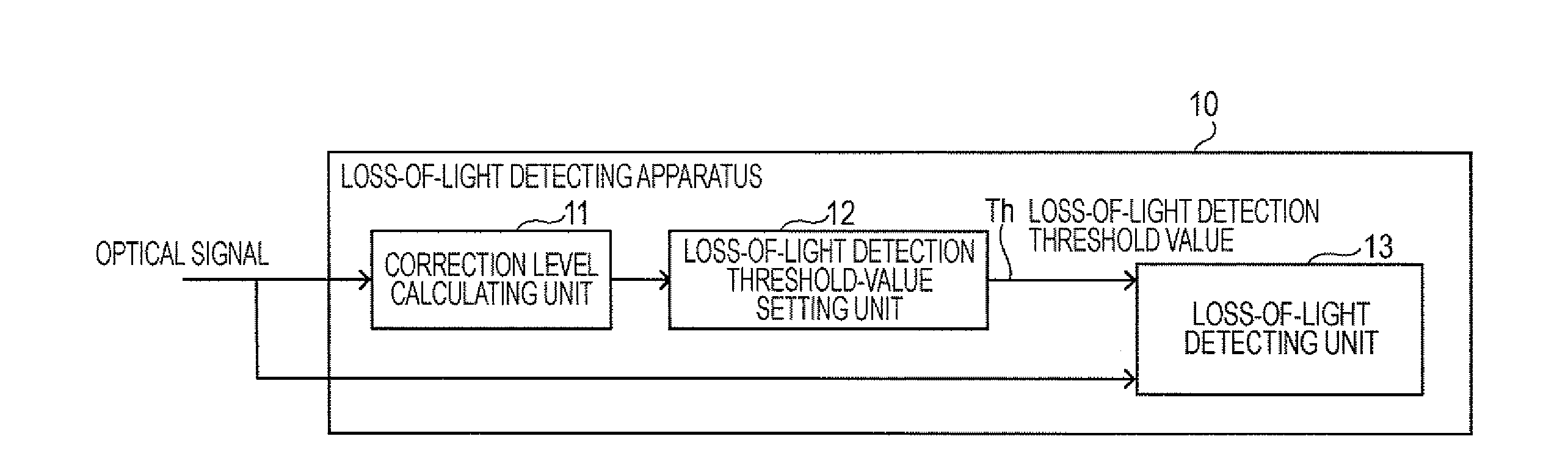
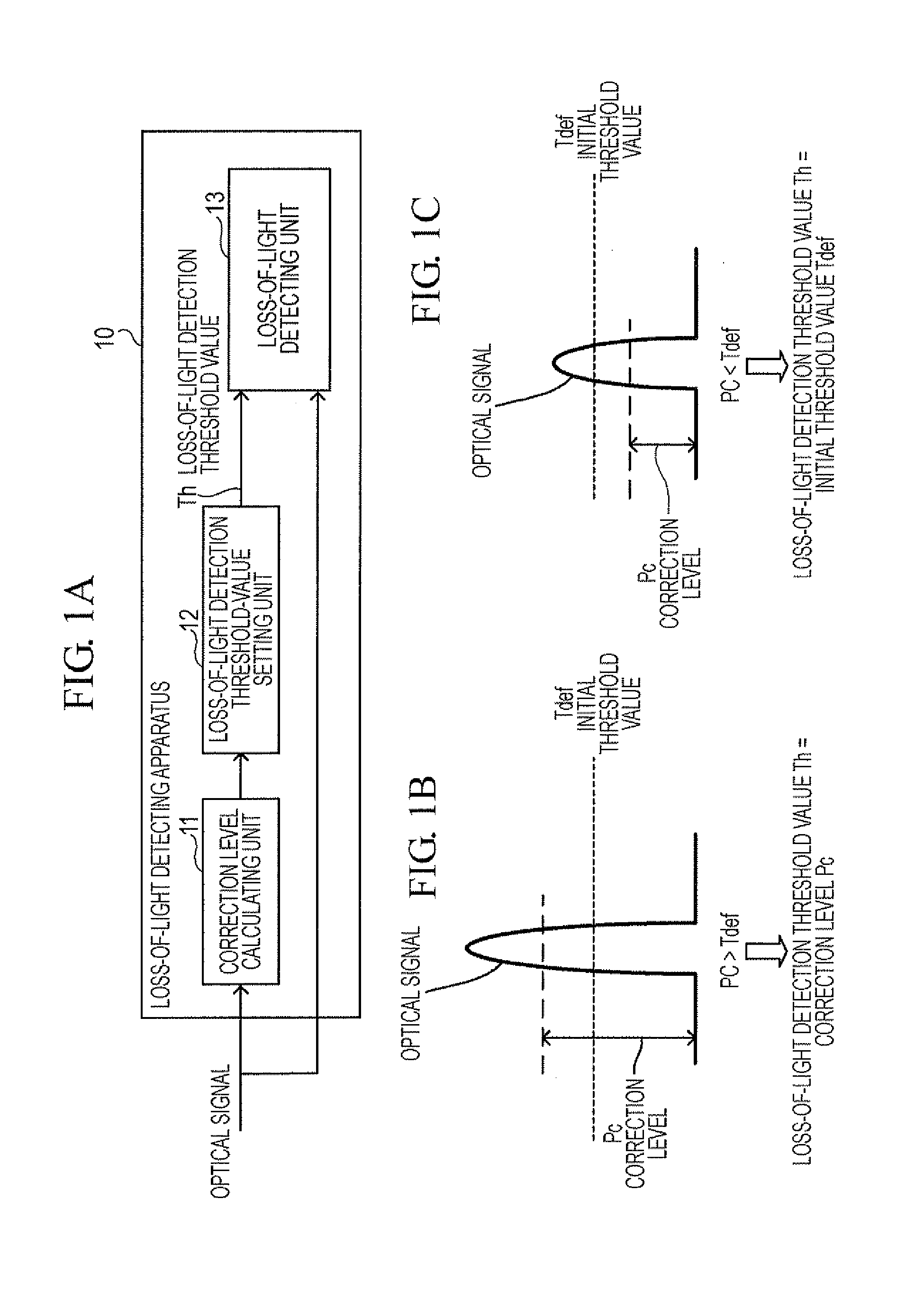
[0052]The configuration of the transponder to which the loss-of-light detecting apparatus 10 is applied will now be described. The loss of light is hereinafter sometimes referred to as “LOL”.

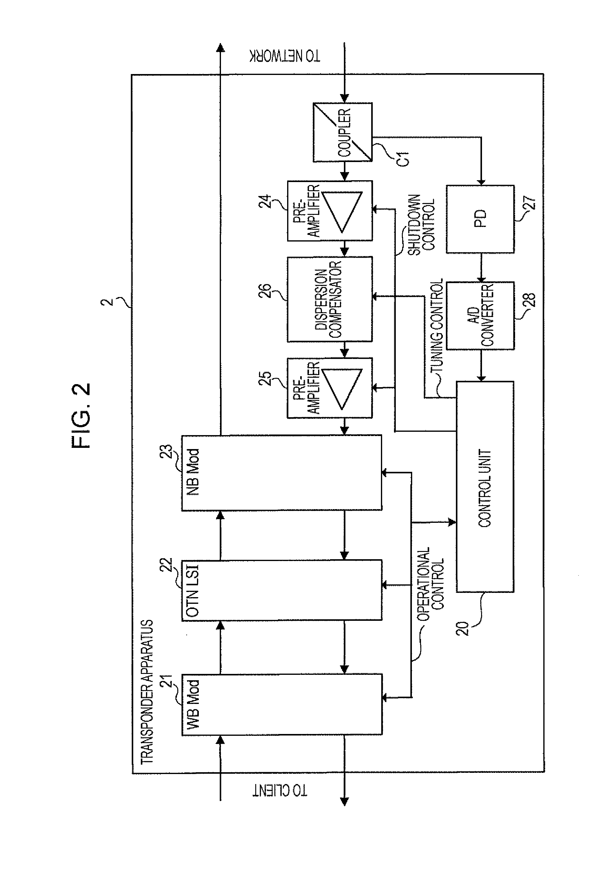
[0053]FIG. 2 is a block diagram showing an example of the configuration of a transponder device 2. The transponder device 2 is, for example, an optical transmission apparatus conforming to the OTN standard based on the WDM optical transmission. The transponder device 2 can be used as the transponders 51-1 to 51-n and the transponders 54-1 to 54-n described above with reference to FIG. 16.

[0054]The transponder device 2 includes a wideband module (WB Mod: wideband optical interface module) 21, a OTN large scale integration (LSI) 22, a narrowband module (NB Mod: narrowband optical interface module) 23, a coupler C1, pre-amplifiers 24 and 25, a dispersion compensator 26, a photodetector (PD) 27, an analog-to-digital (A / D) converter 28, and a control unit 20.

[0055]The WB Mod 21 performs optical-to-e...

second embodiment

[0090]The operation of a transponder to which the loss-of-light detecting apparatus 30 is applied will now be described. The configuration of the transponder is the same as that of the transponder device 2 shown in FIG. 2. The functions of the input-of-light detecting unit 31, the correction threshold value generating unit 33, the loss-of-light detection threshold-value setting unit 34, and the loss-of-light detecting unit 35 in FIG. 6A are included in the control unit 20 shown in FIG. 2, and the function of the main signal component determining unit 32 in FIG. 6A is included in the NB Mod 23 shown in FIG. 2.

[0091]The transponder device 2 uses an R_IN_ALM signal of the NB Mod 23 only at the initial setup. The R_IN_ALM signal is output from a clock and data recovery (CDR) circuit in the NB Mod 23. The R_IN_ALM signal is set to “L” when a data component (main signal component) is detected from an input optical signal and is set to “H” when the input optical signal includes only the A...


PUM


Abstract

According to an aspect of an embodiment, an apparatus comprises: a correction level calculating unit that calculates a correction level, which is the input light level necessary to meet an optical signal-to-noise ratio at the maximum level of an optical noise signal; a loss-of-light detection threshold-value setting unit that compares the correction level with an initial threshold value to set a loss-of-light detection threshold value used in detection of any loss of light on the basis of the comparison result; and a loss-of-light detecting unit that compares the level of an input optical signal with the loss-of-light detection threshold value to determine that any loss of light is caused if the level of the input optical signal is lower than the loss-of-light detection threshold value.

Description

BACKGROUND OF THE INVENTION[0001]1. Field of the Invention[0002]The present invention relates to loss-of-light detecting apparatuses and, more particularly, to a loss-of-light detecting apparatus detecting any loss of light.[0003]2. Description of the Related Art[0004]A basic architecture for optical transmission called Optical Transport Network (OTN) according to International Telecommunication Union Telecommunication Standardization sector (ITU-T) recommendations is used as an optical core network and development of the OTN has been advanced in recent years. In the OTN based on Wavelength Division Multiplexing (WDM) optical transmission, not only signals in telephone services but also signals in Internet Protocol (IP) or Ethernet® services can be processed.[0005]FIG. 16 is a block diagram showing the configuration of a typical WDM apparatus. The WDM apparatus 50 includes a transponder unit 51 and a WDM unit 52 at the transmission side and includes a WDM unit 53 and a transponder u...

Claims


Application Information

Patent Timeline
Patent Type & Authority Applications(United States)
IPC IPC(8): H04B10/08H04B10/07H04B10/079H04B10/40H04B10/50H04B10/60H04B10/69
CPCH04B10/0791
Inventor KASEZAWA, AKIHIDE
Owner FUJITSU LTD
Why Eureka
Try Eureka