Constructions Means

a construction means and construction technology, applied in the direction of rod connections, portable percussive tools, key-type connections, etc., can solve the problem that the slots do not provide partitions, and achieve the effect of smoother mounting, simple mounting and strain, and fastness

Active Publication Date: 2008-09-25
PIN2PIN
View PDF13 Cites 10 Cited by
  • Summary
  • Abstract
  • Description
  • Claims
  • Application Information

AI Technical Summary

Benefits of technology

[0013]This invention replaces the screw function present in clamping rings of the prior art by providing a wedge system to the clamping element which system is considerably faster, smoothe

Problems solved by technology

These slots do not pr

Method used


Image

  • Constructions Means
  • Constructions Means
  • Constructions Means

Examples


second embodiment

[0058]FIG. 18 shows a locking means of the invention.

THE CLAMPING ELEMENT HAS BEEN CONTRUED IN ACCORDANCE WITH THE FOLLOWING

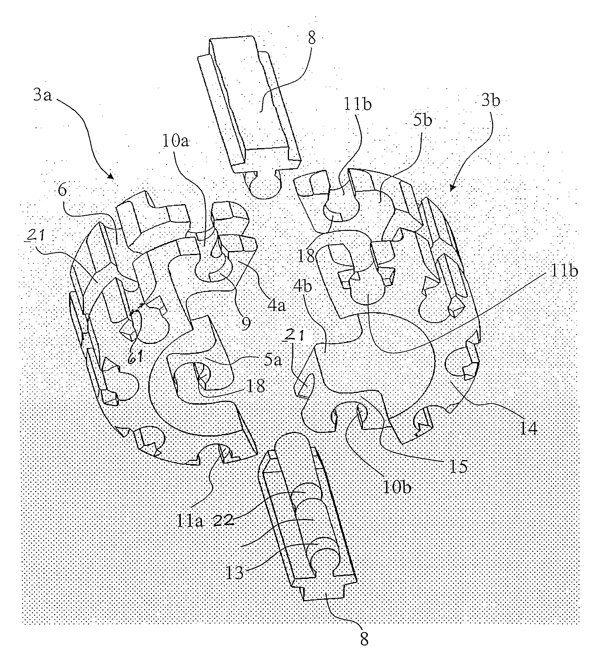
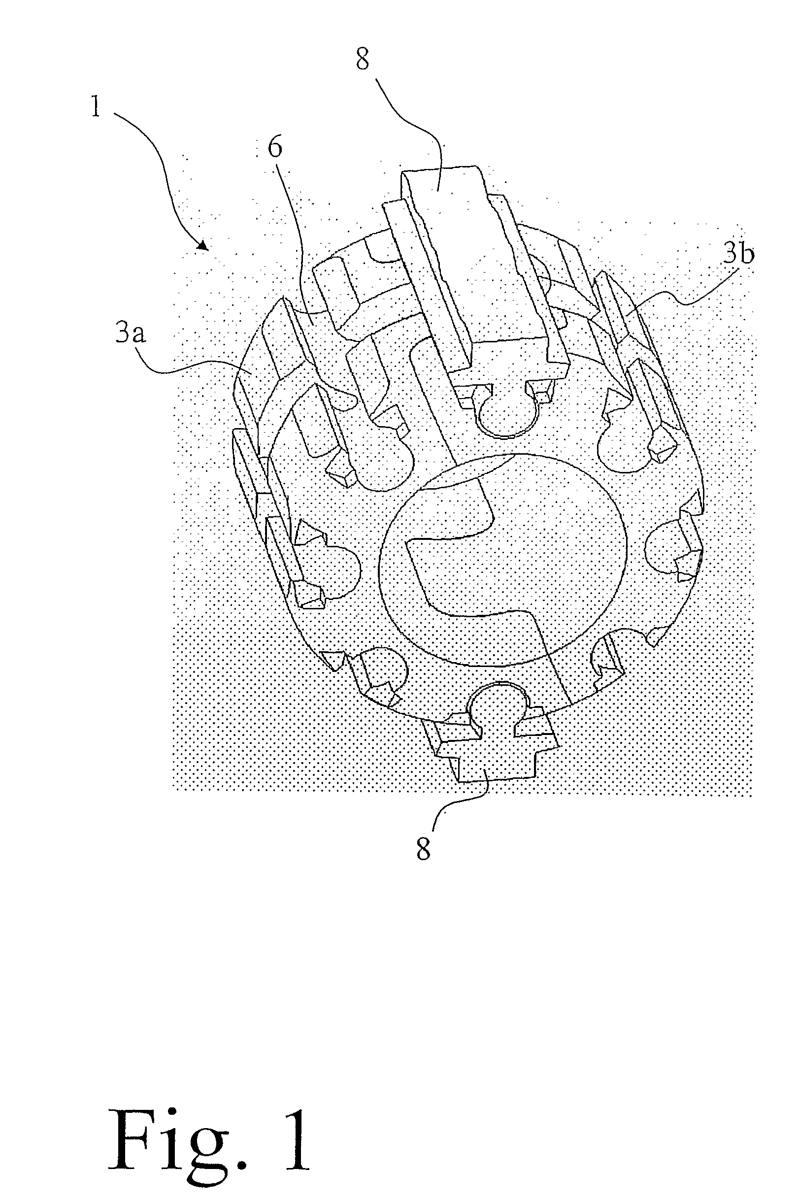
[0059]The clamping element 1 has been designed as an openable ring as shown In FIGS. 1 to 16, which element can be secured to e.g., cylindrical objects 2 (e.g., round staffs or wires). The clamping element 1 consists of, in this embodiment, of two identically equal parts, which will be named “ring halves”3a and 3b, in the following.

[0060]One end of the ring halves 3a and 3b are provided with a protrusion 4, while the other end thereof is provided with a recess 5. The two ring halves 3a and 3b are joined onto a cylindrical object 2 by placing first one ring half 3a and then the further equal ring half 3b (cf FIGS. 3 to 7) to the cylindrical object 2 with or without a snapping effect, which will be explained further below, whereby the protrusion 4a is brought into the corresponding recess 5ab and the protrusion 4b is brought into the corresponding recess 5a and a...

first embodiment

[0073]In the first embodiment above, the clamping element has been shown having two ring halves, whereby it is, however, apparent that one may use a sidewise open ring which is thread over the rod object and which is locked by means of one locking bar only (cf FIGS. 8-9)

[0074]The locking bars 8 have normally a substantially cylindrical shape but with an ingoing waist, which leads to that the locking bar draws the outer parts of the slot towards the centre, which means that the clamping element keep together even better. The partition slots as well as the other undercut slots in the longitudinal direction of the element is 0.5 to 10% narrower in the middle, preferably 1 to 6%, more preferably 2 to 5%, still more preferably 3 to 4% narrower in the middle. The undercut slot may also have a slot profile the narrower part of which has a width corresponding to 40 to 80%, preferably 65 to 70% of the wider part of the slot profile.

[0075]The ratio length to diameter—i.e., the axial longitudi...


PUM


Abstract

A construction element in the form of an openable clamping element (1) being applicable to a primary object and including at least one clamping element (1) surrounding the primary object and a locking element, characterized in that the clamping element (1) contains at least one partition slot being a parting line of the clamping element, and a locking bar (8) being introducible into the slot, whereby the slot is oriented in parallel to the through going axis of the clamping element.

Description

TECHNICAL FIELD[0001]The present invention relates to a means for quick mounting and quick demounting joining around an item by means of surrounding clamping action.BACKGROUND OF THE INVENTION[0002]It is well known that a ring which is tensioned around an object can be secured in a very robust way. Such rings are called clamping rings herein. The desire concerning these clamping rings are that they should be readily mounted at a desired site and position on the object, that they shall have a high strength and be safely secured thereto, that it shall be simple to attach other objects thereto as well as it shall, if so needed, be simple to demount the element. These types of elements, often in ring shape, are used e.g., when mounting post mounted road signs, cable clips at automotive batteries, post mounted traffic lights, fastening means for motorcycle accessories etc. Hose clamps belong to this category as well.[0003]Toy construction systems are a technical field as well where clamp...

Claims


Application Information

Patent Timeline
IPC IPC(8): F16B3/00
CPCF16B2/10Y10T403/587Y10T403/345Y10T403/341Y10T403/7035Y10T403/5773Y10T403/7021Y10T403/69F16B2200/71F16B2/08
Inventor BERG, TOMAS
Owner PIN2PIN
Why Eureka
Try Eureka