Connector

a technology of connecting rods and connectors, applied in the direction of coupling contact parts, coupling device connections, coupling contact members, etc., can solve the problems of easy generation of variations in assembly accuracy, easy generation of low-profile connectors, and easy generation of contact failures between fpc and the lower arm, so as to improve contact reliability and reduce the width of the base. , the effect of high accuracy

Inactive Publication Date: 2008-09-25
DAIICHI SEIKO CO LTD
View PDF2 Cites 19 Cited by
  • Summary
  • Abstract
  • Description
  • Claims
  • Application Information

AI Technical Summary

Benefits of technology

[0008]In one or more embodiments of the invention, a low profile connecter has a connecter having high contact reliability, small floor area, and uniform operating characteristics.

Problems solved by technology

Therefore, in the connector, there is a risk of generating contact failure between FPC and the lower arm portion 23.
Therefore, it is necessary that the surroundings of the insertion hole 32 be made of a thick resin, which hardly achieves the low-profile connector.
Therefore, unfortunately variations in assembly accuracy are easily generated to hardly obtain the connector having uniform operating characteristics.

Method used


Image

  • Connector
  • Connector
  • Connector

Examples


Embodiment Construction

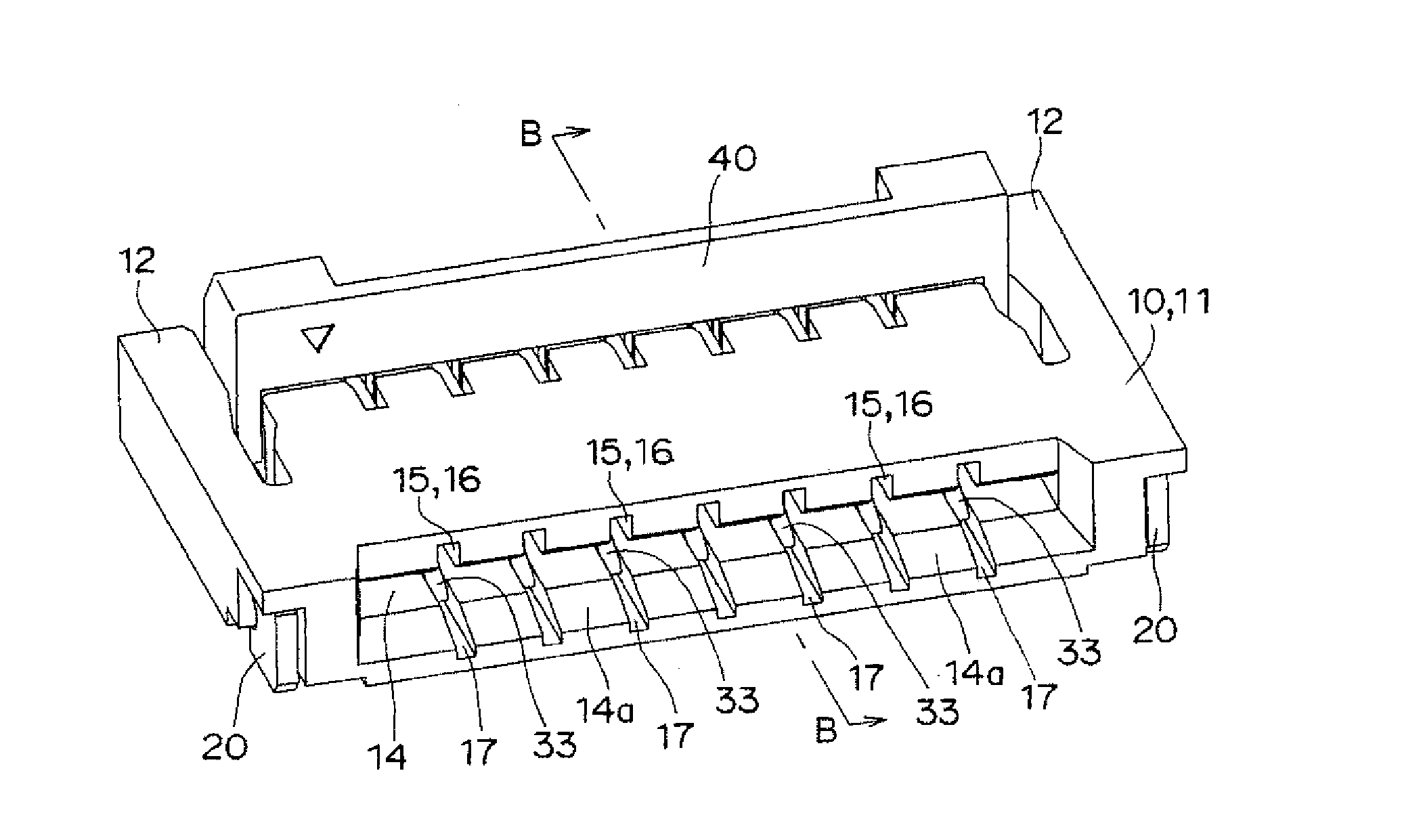
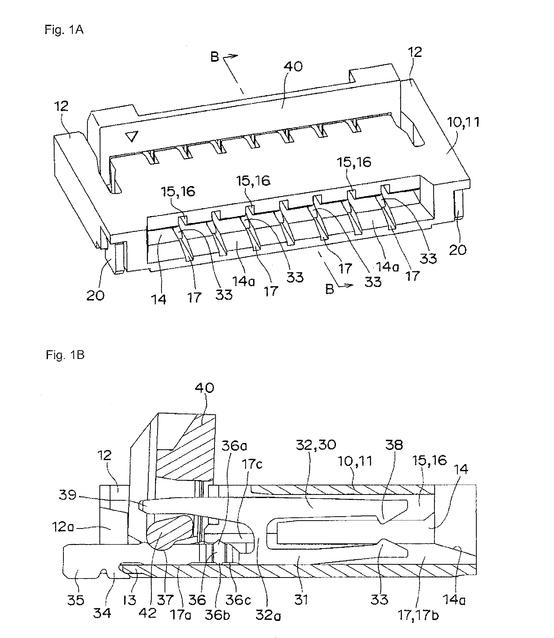
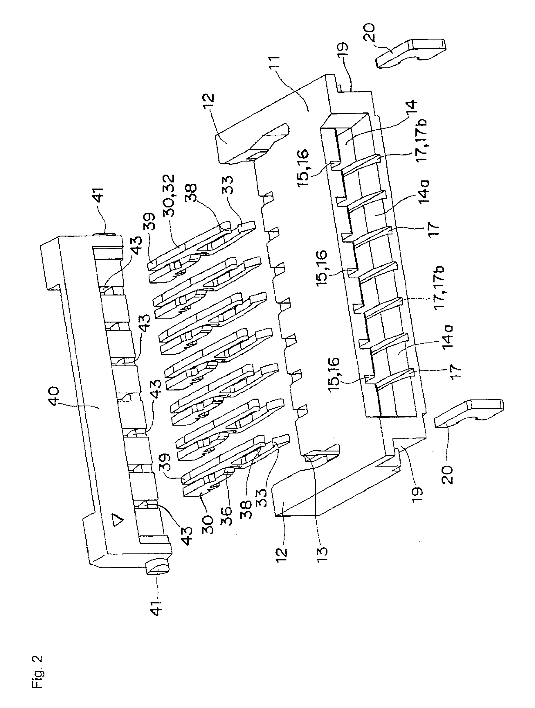
[0027]An embodiment of the invention will be described below with reference to the accompanying drawings. As shown in FIGS. 1 to 3, a connector 10 according to a first embodiment of the invention mainly includes a base 11, reinforcing fittings 20, connecting terminals 30, and a manipulation lever 40.

[0028]As shown in FIG. 6, in the base 11, elastic arm portions 12 and 12 are extended in parallel toward a backside from one-side edge portions in end faces on both sides, and a guide plate 13 is laterally projected from a lower edge portion of the backside. In an inward surface of the elastic arm portion 12, a guiding tapered surface 12a is formed in a front-end edge portion and a bearing notch 12b is formed at the back of the guiding tapered surface 12a. In the base 11, an opening 14 in which a front-end portion 51 of FPC 50 can be inserted is provided in a front surface. A guiding tapered surface 14a is formed in a lower-side edge portion of the opening 14. In the base 11, plural inse...


PUM


Abstract

A connector has a base having insertion holes in parallel at a predetermined pitch, A connector has a base having insertion holes in parallel at a predetermined pitch, H-shape connecting terminals laterally inserted into the insertion holes, each connecting terminal having a support contact piece on a lower side of the connecting terminal, a manipulation contact piece on an upper side of the connecting terminal, and a coupling portion which couples the support contact piece and the manipulation piece, and a manipulation lever rotatably attached to a bearing portion of the support contact piece disposed on a first side of the base. A latching pawl, formed on a first end of the support contact piece, is latched on an edge portion of the base. A flexible board is inserted from an opening on a second side of the base. The manipulation lever manipulates the manipulation contact piece to bring an end portion of the manipulation contact piece into pressure-contact with the flexible board.

Description

BACKGROUND OF THE INVENTION[0001]1. Field of the Invention[0002]The present invention relates to a connector, particularly to a connector connected to a connecting portion provided in parallel in a front-end portion of a flexible printed circuit board (hereinafter referred to as “FPC”).[0003]2. Description of the Related Art[0004]Conventionally, for example, Japanese Patent Application Laid-Open No. 2004-342426 discloses a connector As shown in FIG. 6C of Japanese Patent Application Laid-Open No. 2004-342426, a fitting portion 23c located on one end side of a lower arm portion 23 is engaged with an edge portion on one side of a main body portion 31, the other end portion of the lower arm portion 23 is inserted in an insertion hole 32 of the main body portion 31, and only an upper arm portion 21 is rotatably supported.[0005]However, in the connector mentioned above, when the other end portion of the lower arm portion 23 is used as a contact, the lower arm portion 23 cannot follow FPC...

Claims


Application Information

Patent Timeline
Patent Type & Authority Applications(United States)
IPC IPC(8): H01R13/629
CPCH01R12/778H01R12/88H01R12/721H01R12/78
Inventor MATOBA, MASATOYOKOIGAWA, ATSUSHI
Owner DAIICHI SEIKO CO LTD
Why Eureka
Try Eureka