
Rotor for a threshing system of an agricultural combine and method of making the same

a technology of combine threshing and rotor, which is applied in the direction of metal-working apparatus, agriculture tools and machines, and agricultural machinery, can solve problems such as degree of misshapenness, and achieve the effect of optimal roundness and dimensional control

Active Publication Date: 2008-09-25
BLUE LEAF I P
View PDF17 Cites 0 Cited by
  • Summary
  • Abstract
  • Description
  • Claims
  • Application Information

AI Technical Summary

Benefits of technology

[0006]What is disclosed is a rotor for a threshing system of an agricultural combine which avoids one or more of the problems set forth above, particularly irregularities and eccentricity in the outer surface of the rotor and water infiltration, and a method for making the same which is simple and economical.
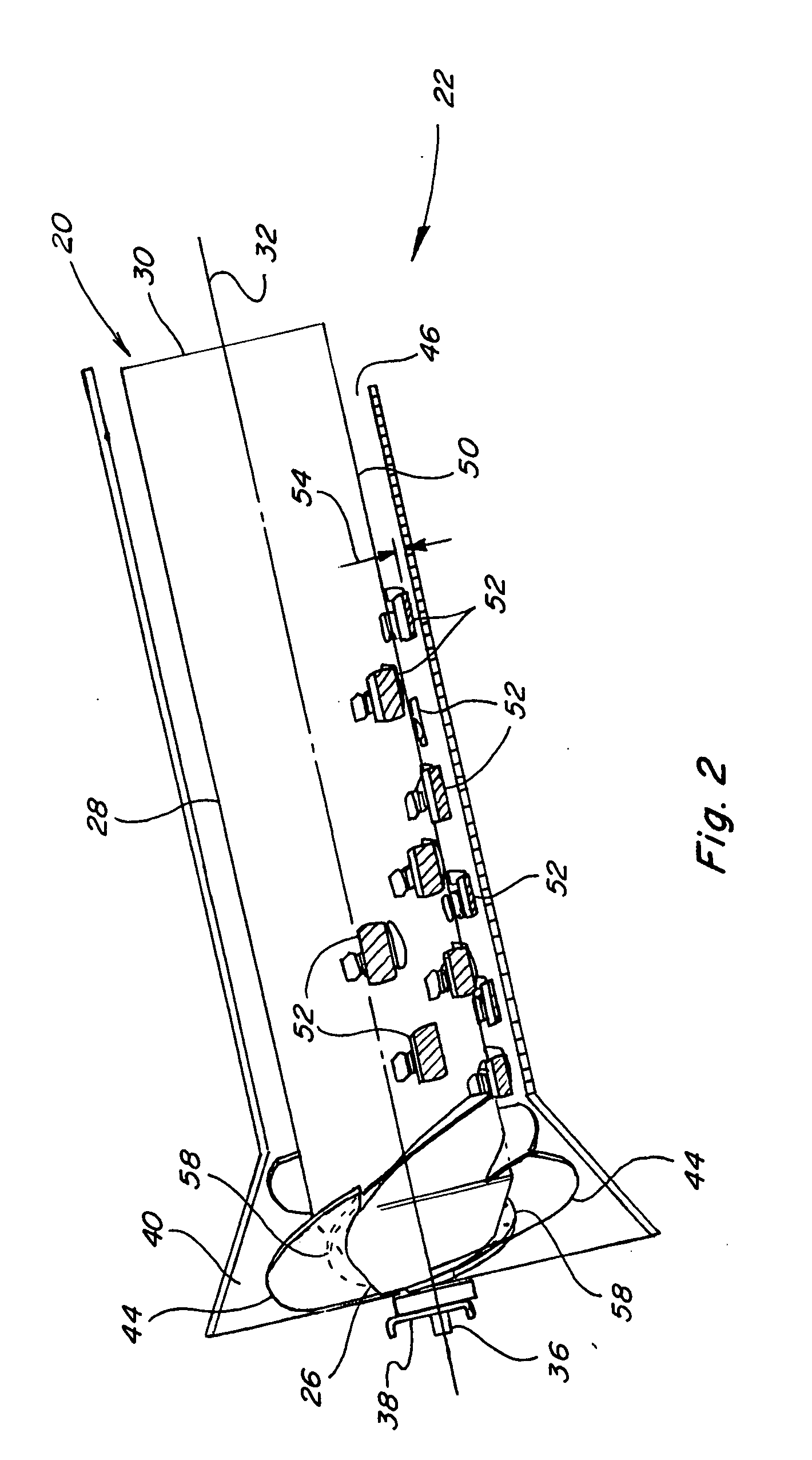
[0007]According to a preferred aspect of the invention, the body of the rotor is of simplified, three part press fit construction including an inlet segment to be disposed in an inlet region of the threshing system, a main body segment which will incorporate threshing elements therearound for performing the threshing function, and a bulkhead to be connected to a drive mechanism operable for rotating the rotor. The inlet segment, main body segment and bulkhead are configured so as to facilitate press fit assembly thereof concentric about a rotational axis about which the rotor will be rotated during operation, while also minimizing eccentricities of those components. Thus the manufacture of the rotor is simplified by the elimination of the need for an internal skeleton structure and associated internal welds and / or fasteners.
[0009]The main body segment is preferably a tubular member having an outer surface which in a preferred embodiment is cylindrical, and supports an array of threshing elements therearound, the body segment having a first open end portion and a second open end portion. The first open end portion includes a peripheral surface therearound configured and sized to be press fit to the tapered peripheral surface of the lip of the inlet segment concentric about the rotational axis. The open end portion of the tubular main body segment is additionally configured to be sufficiently compliant or conformable to the more rigid lip of the inlet segment, such that when press fit together, the lip will act essentially as a forming or shaping mandrel for the end of the main body segment, the end portion of the main body segment will conform in shape to the transverse shape (preferably round) of the lip and will have an overall transverse dimension through the rotational axis corresponding with that portion of the lip, which dimension is controllable by the extent to which the main body segment is press fit to the inlet segment. In this latter regard, it is anticipated that the transverse dimensions and shapes of the open ends of different main body portions before being press fit with the inlet section will typically vary, as a result of a variety of causes, which can include material variances, manufacturing tolerances, stress, and the like, while the transverse dimension and shape of the lip will be substantially more precise and consistent, as a function of its shape and sized, and that its manufacture can be more precisely controlled. For instance, some body segments are likely to be larger than a nominal transverse dimension, and some smaller, and some will have some degree of misshapenness, such as eccentricity.
[0012]The skirt has a peripheral surface therearound for engaging an opposing surface extending around the open end of the main body segment, which peripheral surface preferably has an axially extending tapered portion therearound having a predetermined overall shape (preferably round), and a predetermined transverse dimension through the axis of the hub for facilitating the press fitting thereof to the main body segment. This transverse dimension can be the same or nearly the same as that of the tapered surface of the lip of the inlet segment for a main body segment having a cylindrical shape, or otherwise having the same size open end portions.

Problems solved by technology

For instance, some body segments are likely to be larger than a nominal transverse dimension, and some smaller, and some will have some degree of misshapenness, such as eccentricity.

Method used


Image

  • Rotor for a threshing system of an agricultural combine and method of making the same
  • Rotor for a threshing system of an agricultural combine and method of making the same
  • Rotor for a threshing system of an agricultural combine and method of making the same

Examples


Embodiment Construction

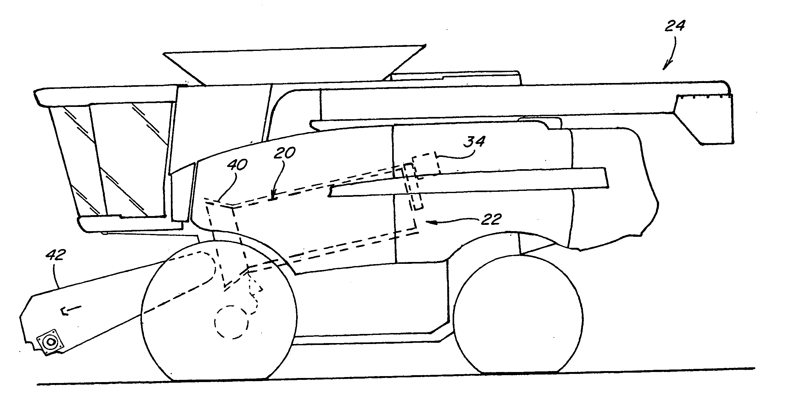
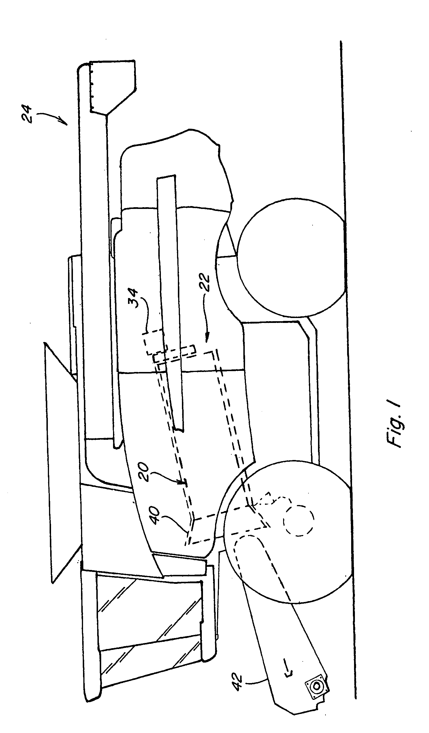
[0035]Turning now to the drawings wherein aspects of a preferred embodiment of a rotor 20 and method of making the same according to the present invention are shown, in FIG. 1, rotor 20 is shown in a threshing system 22 of a representative agricultural combine 24. Agricultural combine 24 is representative of an axial flow type combine including a single, fore and aft extending rotor, but it should be understood that it is contemplated that rotor 20 and the method of the invention can likewise be used with rotors of other types of combines, including, but not limited to, conventional types wherein one or more rotors of the invention will be mounted in a transverse orientation within a body of the combine.

[0036]Referring also to FIGS. 2, 3 and 4, rotor 20 generally includes an inlet segment 26 which is forwardly located in this application; a main body segment 28, and a bulkhead 30, which is rearwardly located. Rotor 20 is supported for rotation about a fore and aft extending inclined...


PUM

PropertyMeasurementUnit
Fractionaaaaaaaaaa
Massaaaaaaaaaa
Lengthaaaaaaaaaa

Abstract

A rotor for a threshing system of an agricultural combine and method for making the same, including a body of simplified, three part press fit construction including an inlet segment, a main body segment having threshing elements therearound, and a bulkhead to be connected to a drive mechanism. The inlet segment, main body segment and bulkhead are configured so as to facilitate press fit assembly thereof concentric about a rotational axis about which the rotor will be rotated during operation, while also minimizing eccentricities of those components. As a result, the manufacture of the rotor is simplified by the elimination of the need for an internal skeleton structure and associated welds and / or fasteners.

Description

TECHNICAL FIELD[0001]This invention relates generally to a rotor for the threshing system of an agricultural combine, and a method of making the same.BACKGROUND ART[0002]Many agricultural combines use a rotary threshing or separating system. The system typically includes at least one rotor drivingly rotated within a perforated concave spaced radially outwardly thereof. The rotor will often have a frusto-conical inlet end having a helical flight or flights therearound for conveying a flow of crop material into a space between the rotor and the concave. The main body of the rotor will typically have one or more cylindrical or frusto-conical outer surface portions including threshing elements which protrude radially outwardly therefrom into the space and which are arranged in a pattern or array for conveying a mat of the crop material along a helical path through the space, while cooperating with features of the concave, e.g. bars or ribs, to separate larger components of the crop, nam...

Claims


Application Information

Patent Timeline
IPC IPC(8): A01F12/18
CPCA01F12/18Y10T29/49908A01F12/22
Inventor MURRAY, CRAIG E.LINDER, CHARLESMATOUSEK, ROBERT A.EPPERLY, MARK S.
Owner BLUE LEAF I P
Learn More