Spinal stabilization system with rigid and flexible elements

a technology of rigid and flexible elements and stabilization systems, applied in the field of spinal stabilization systems, can solve the problems difficult to pull the cord off the rigid element, and achieve the effect of increasing the surface area in contact and facilitating the retaining of the cord

Active Publication Date: 2008-09-25
ZIMMER BIOMET SPINE INC
View PDF56 Cites 178 Cited by
  • Summary
  • Abstract
  • Description
  • Claims
  • Application Information

AI Technical Summary

Benefits of technology

[0008]In some embodiments, the end portion of the flexible element is received over the end portion of the rigid element. For example, the flexible element may be a cord constructed from polymer fibers braided over the end portion of the rigid element. To further facilitate retaining the cord on the rigid element, the fibers may be ultrasonically cut and/or ultrasonically welded

Problems solved by technology

Such an arrangement increases the amount of surface area in contact between the cord

Method used


Image

  • Spinal stabilization system with rigid and flexible elements
  • Spinal stabilization system with rigid and flexible elements
  • Spinal stabilization system with rigid and flexible elements

Examples


Embodiment Construction

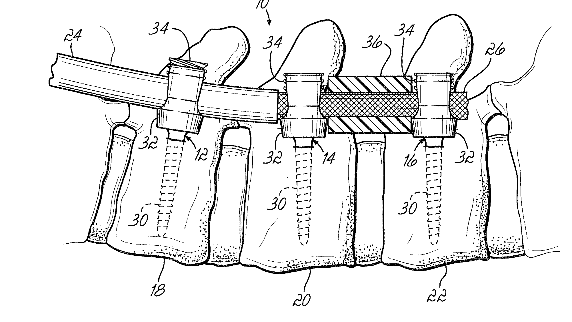
[0025]FIG. 1 shows one embodiment of a spinal stabilization system or construct 10 according the invention within a patient's body. The stabilization system 10 includes first, second, and third anchor members 12, 14, 16 secured to respective first, second, and third vertebrae 18, 20, 22 within the patient's body. The anchor members 12, 14, 16 may be any type of anchor such as a screw or hook designed to cooperate with a rigid element 24 or a flexible element 26 to stabilize a portion of the spine. For example, in the embodiment shown in FIG. 1, the anchor members 12, 14, 16 are pedicle screw assemblies each having a screw body 30, a housing or retainer 32 coupled to the screw body 30, and a set screw 34. Each housing 32 receives the rigid element 24 or the flexible element 26, which are secured to the associated housing 32 by one of the set screws 34. One example of this type of pedicle screw arrangement is the Optima® Spinal Stabilization System available from Zimmer, Inc. of Warsa...


PUM


Abstract

A spinal stabilization system generally comprises first and second anchor members configured to be secured to first and second vertebrae within a patient's body, a flexible element secured to the first anchor member, and a rigid element secured to the second anchor member. An end portion of the rigid element is coupled to an end portion of the flexible so that the system is able to provide both rigid and dynamic stabilization. The coupling is maintained even if the flexible element relaxes after a period of time within the patient's body.

Description

FIELD OF THE INVENTION[0001]This invention relates to spinal stabilization systems, and more particularly to such systems including both a rigid element and a flexible element.BACKGROUND[0002]The spinal column is a highly complex system of bones and connective tissues that provides support for the body and protects the delicate spinal cord. The spinal column includes a series of vertebrae stacked one on top of the other, each vertebral body including an inner or central portion of relatively weak cancellous bone and an outer portion of relatively strong cortical bone. The vertebrae in the cervical, thoracic, and lumbar regions of the spine are separated by intervertebral discs, which serve as cushions between adjacent vertebrae to dampen compressive forces experienced by the spine. A vertebral canal containing the spinal cord is formed by the intervertebral foramen of the vertebrae. In spite of the complexities, the spine is a highly flexible structure, capable of a high degree of c...

Claims


Application Information

Patent Timeline
IPC IPC(8): A61B17/70A61B17/58A61B17/04
CPCA61B17/7005A61B17/7008A61B17/705A61B17/7031A61B17/7022A61B17/7004A61B17/7019A61B17/7032A61B17/7034
Inventor ZYLBER, EMMANUELEGLI, THOMASTHOMPSON, ROSEMARYFROEHLICH, MARKUSCICERCHIA, GIUSEPPEDANT, JACK A.VIKER, THOMAS O.LEY, KEVIN R.
Owner ZIMMER BIOMET SPINE INC
Why Eureka
Try Eureka