
Lawn Mower

a lawnmower and mower technology, applied in the field of lawnmowers, can solve the problems of not being able to mowing work on a footpath, affecting the work efficiency of the lawnmower, and loud engine noise at the time of work,

Inactive Publication Date: 2008-10-02
SUBARU CORP
View PDF17 Cites 9 Cited by
  • Summary
  • Abstract
  • Description
  • Claims
  • Application Information

AI Technical Summary

Benefits of technology

The invention is a lawn mower with a detachable power source that can be connected to either an engine or an electric motor. The mower has a main body with a cutter, a power source, and joint means for attaching the power source to the main body. The joint means includes a centrifugal clutch and a detachable joint case for the power source. The mower also has an operation arm with a driven shaft and a cutter, and a detachable joint case for the power source. The joint case has a centrifugal clutch with a first member, a second member, and a third member that engages when the centrifugal force is applied. The detachable joint cases and the power source are fastened by a fasten member. The technical effect of the invention is that users can select between an engine and an electric motor for the power source based on the working circumstance, making the mower more versatile and user-friendly.

Problems solved by technology

However, engine noise at the time of work is louder than a motor drive.
Thus, the lawn mower which has the electric motor as the power source does not generate a loud noise, however, the place where the lawn mower is used is limited to around a house.
For this reason, it is not suitable for mowing work on a footpath in fields where there is no supply outlet.
In contrast, the lawn mower which has the engine as the power source can be used even if there is no power supply outlet close to the working place for mowing weeds and grass, however, when mowing work is carried out in the city, the noise problem may bother the neighbors.

Method used


Image

  • Lawn Mower
  • Lawn Mower
  • Lawn Mower

Examples


Embodiment Construction

[0020]A preferred embodiment of the present invention is explained with figures. However, the scope of the invention is not limited by the illustrated embodiments of the figures.

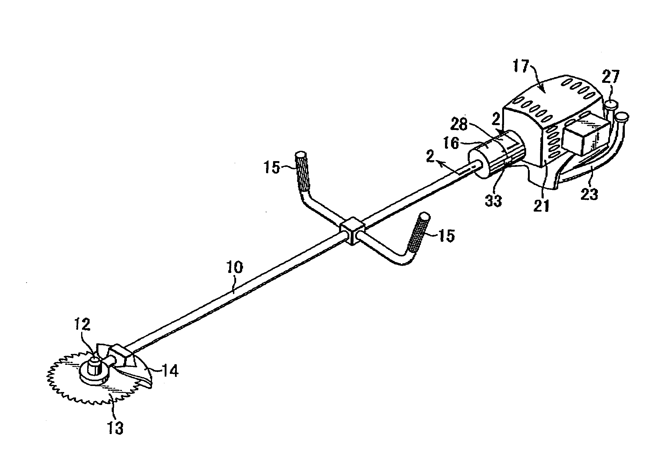
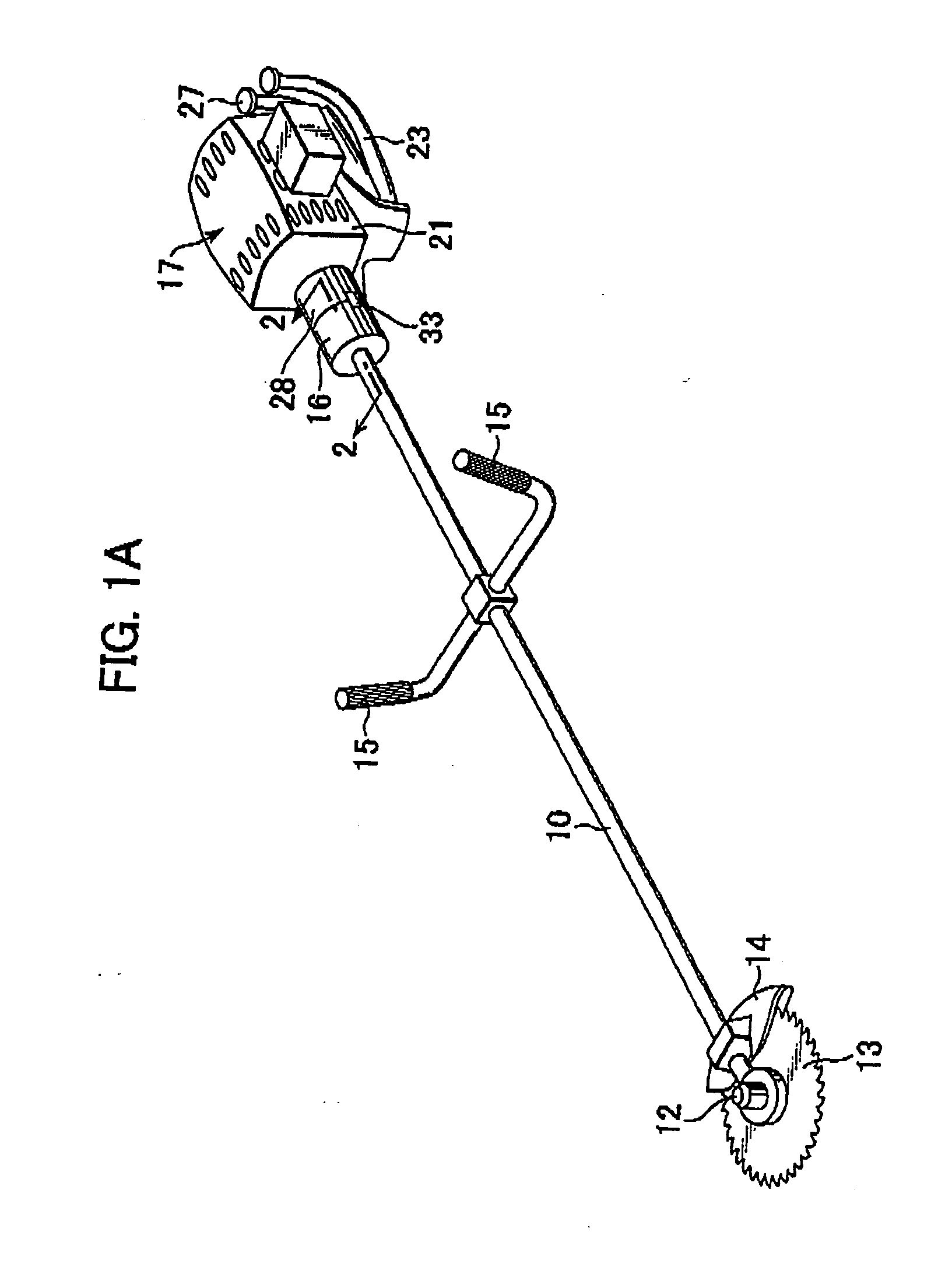
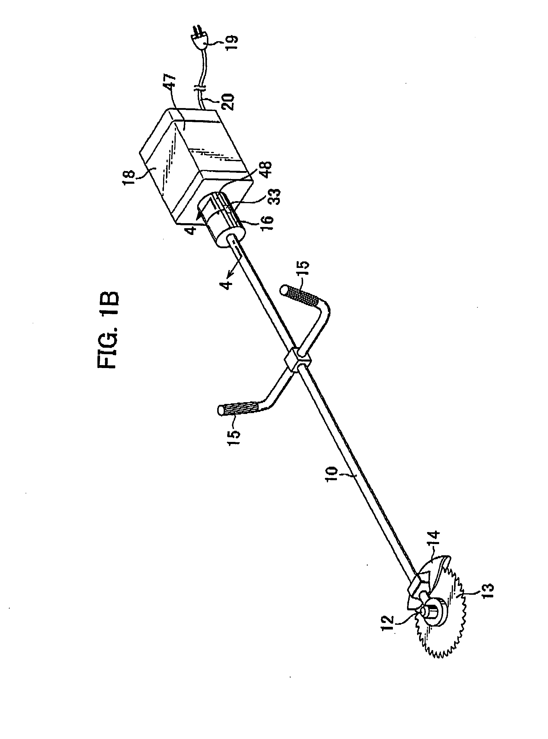
[0021]A lawn mower shown in FIGS. 1(A) and 1(B), which is the arm coupling type, comprises an operation arm 10 as a main body, a driven shaft 11 rotatably provided inside the operation arm 10 as shown in FIG. 2, a discoid metal cutter 13 installed on the driven shaft 11 at one end of the operation arm 10, an arm side joint case 16 provided at the other end of the operation arm 10 with a large diameter than the operation arm 10 and either one of an engine 17 and an electric motor 18 selectively installed on the operation arm 10 through the joint case 16. The operation arm 10 is formed of a hollow shaft. A holder 12 is attached to the one end of the operation arm 10. The metal cutter 13 has a plurality of saw-edged cutting tooth on its outer peripheral and is rotatably attached to the holder 12. The cutter 13 ...


PUM


Abstract

A lawn mower comprises an operation arm, a driven shaft rotatably supported inside the operation arm and having two opposite ends, a cutter operatively connected to one end of the driven shaft, a power source operatively connected to the other end of the driven shaft for generating a drive power to be transmitted to the cutter through the driven shaft, wherein said power source is selective from an engine and an electric motor, an arm side joint case provided on the end of the operation arm, a power source side joint case provided on a housing of the power source and detachably and selectively connected to the arm side joint case, and a centrifugal clutch incorporated in the arm side joint case and having a first member connected to the driven shaft, a second member detachably and selectively connected to the power source and a third member provided to engage the first member and the second member according to the centrifugal force applied thereto.

Description

CROSS REFERENCE TO RELATED APPLICATIONS[0001]This application is a continuation of Ser. No. 11 / 249,385 filed Oct. 14, 2005, which application is incorporated herein by reference in its entirety. Further, the disclosure of Japanese Application No. 2004-301988 filed on Oct. 15, 2004 including the specification, drawing and abstract is incorporated herein by reference in its entirety.FIELD OF THE INVENTION[0002]This present invention is related to a lawn mower, preferably the lawn mower having a structure to be selectively attached one of an engine and an electric motor as a power source.BACKGROUND OF THE INVENTION[0003]A lawn mower, also referred to as a grass mower, is used to mow a weed of a footpath in the fields, bottom weed of the forest or pasture grass. There are two types of the lawn mower, one is an arm coupling type and the other is a direct acting type. As for the arm coupling type, a cutter is attached to one end of an operation arm and a power source is attached to the ot...

Claims


Application Information

Patent Timeline
Patent Type & Authority Applications(United States)
IPC IPC(8): B26B7/00
CPCA01D34/90A01G3/06A01G3/062
Inventor YOSHIDA, KENICHI
Owner SUBARU CORP
Learn More