
Solvent absorbing device and image forming apparatus

a technology of solvent absorbing device and image forming apparatus, which is applied in the direction of vacuum evaporation coating, printing, coating, etc., can solve the problems of recording medium wrinkles, wrinkling of recording medium, and liable to occur, so as to promote the collection of excess solvent, the effect of no decline in absorption properties and prescribed absorption performan

Inactive Publication Date: 2008-10-02
FUJIFILM CORP
View PDF4 Cites 60 Cited by
  • Summary
  • Abstract
  • Description
  • Claims
  • Application Information

AI Technical Summary

Benefits of technology

[0011]The present invention has been contrived in view of these circumstances, an object thereof being to provide a solvent absorbing device and an image forming apparatus whereby there is no decline in the excess solvent absorption performance and excess solvent can be collected reliably.

Problems solved by technology

If the excess solvent is not removed sufficiently, then problems are liable to occur, such as bleeding of the recorded image, wrinkling of the recording medium, and the like.
In particular, when using a non-permeable medium (for example, plastic, metal, glass, or the like) as the recording medium, bleeding is liable to occur in the recorded image, and this may cause deterioration of image quality.
Even in the recording apparatus of this kind, there is a problem in that a satisfactory transferred image cannot be obtained unless the excess solvent on the intermediate transfer body is removed satisfactorily.
In the inkjet recording apparatus based on the two-liquid reaction method particular, since a large amount of solvent is deposited on the surface of the medium, then the aforementioned problems caused by the excess solvent are even more liable to occur.
However, this is problematic in that since the air flows into the absorbing body from all sides, then the suction force is low and it is difficult to collect the excess solvent, unless the surface of the absorbing body is sealed with liquid, or the like.
However, although this resolves the problems associated with Japanese Patent Application Publication No. 2001-179959, since it is only able to suction from a part of the porous body, then while it is possible to collect the excess solvent, it is not possible to dry the porous body sufficiently.
If the porous body is not dried sufficiently, then the absorption performance of the porous body is reduced, and the excess solvent cannot be collected adequately.

Method used


Image

  • Solvent absorbing device and image forming apparatus
  • Solvent absorbing device and image forming apparatus
  • Solvent absorbing device and image forming apparatus

Examples


first embodiment

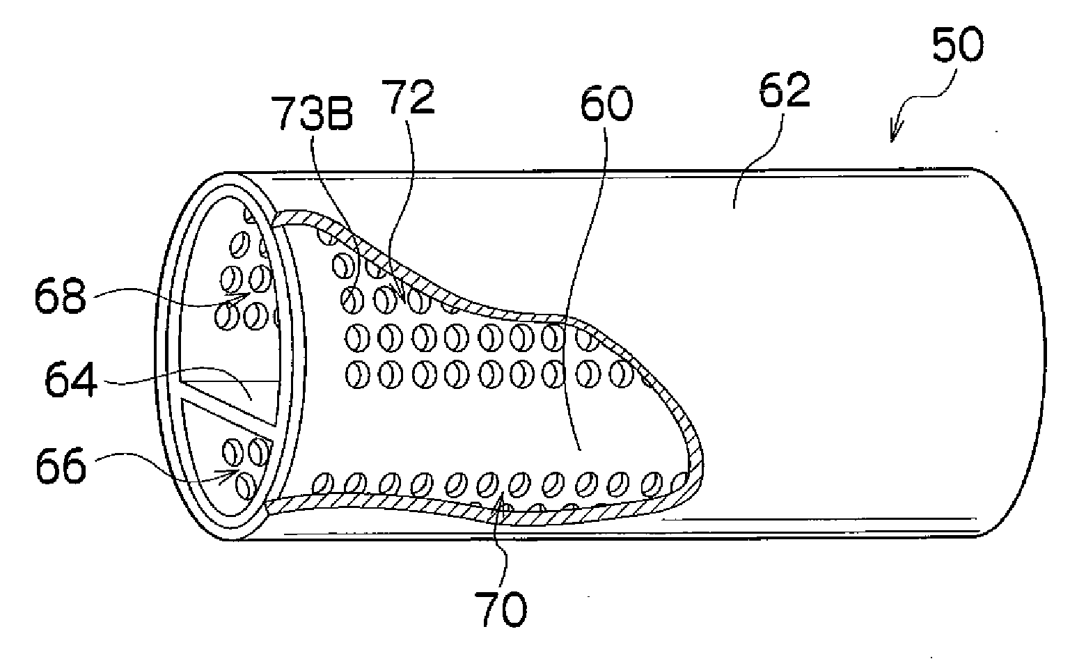
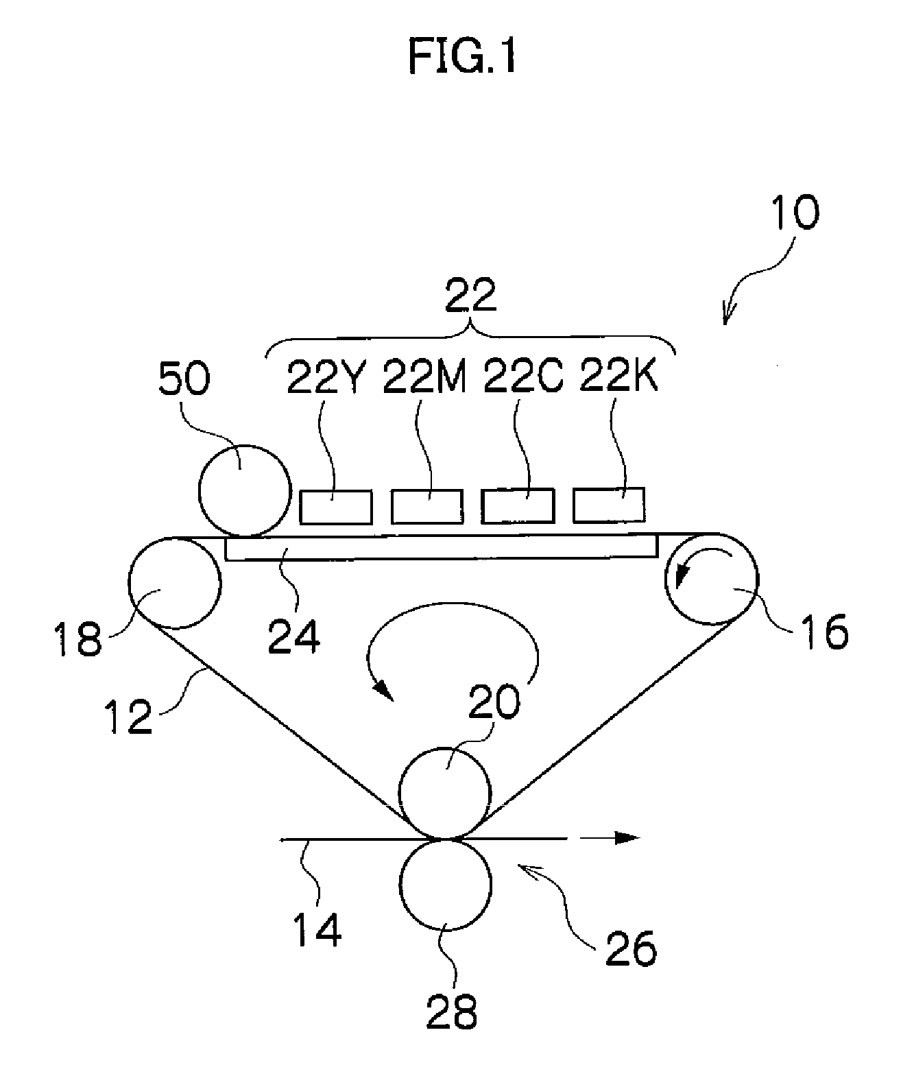
[0080]FIG. 4 is a schematic drawing showing the composition of the solvent absorbing device according to a first embodiment. In FIG. 4, numeral 50 denotes a solvent removing roller, 52 denotes a nonpermeable medium, 54 denotes ink and treatment liquid (coloring material aggregating reaction liquid), 56 denotes coloring material (colorant), and 58 denotes a solvent. The non-permeable medium 52 corresponds to the intermediate transfer body 12 (in FIG. 1) or 12A (in FIG. 3A) or the recording medium 14B (see FIG. 3B), which is used in the above-described inkjet recording apparatus. The coloring material 56 is formed by pigment particles or dye that has aggregated and formed particles. FIG. 4 shows a mode where, when the non-permeable medium 52 having the ink 54 deposited on the surface thereof is conveyed in the medium conveyance direction (the direction of an arrow A in FIG. 4), then a portion of the solvent 58 (the excess solvent) on the non-permeable medium 52 is removed by the solve...

second embodiment

[0102]Next, a solvent absorbing device according to the second embodiment of the present invention is described. Below, the parts common with the first embodiment described above are not explained further, and the following description centers on the characteristic features of the second embodiment.

[0103]FIG. 6 is a schematic drawing showing the composition of the solvent absorbing device according to the second embodiment. In FIG. 6, the parts common or similar with those in FIG. 4 are denoted with the same reference numerals.

[0104]The solvent absorbing device shown in FIG. 6 has a check valve 80 arranged in the partition 64, which divides the interior of the hollow open roller 60 into the first and second spaces 66 and 68, and the suction device 74 is connected only to the first space 66. The check valve 80 is configured to be openable and closeable in accordance with the pressure difference between the first and second spaces 66 and 68, and when the check valve 80 is in the close...

third embodiment

[0109]Next, a solvent absorbing device according to the third embodiment of the present invention is described. Below, the parts common with the above-described embodiments are not explained further, and the following description centers on the characteristic features of the third embodiment.

[0110]FIG. 7 is a schematic drawing showing the composition of the solvent absorbing device according to the third embodiment. In FIG. 7, the parts common or similar with those in FIG. 4 are denoted with the same reference numerals.

[0111]In the solvent absorbing device shown in FIG. 7, the suction device 74 is connected to the first space 66 and a pressurization device 82 is connected to the second space 68. Since the negative pressure is applied to the first space 66 by the suction device 74, then it is possible to promote the collection of the excess solvent by the absorbing body 62 through the first opening section 70. On the other hand, since a positive pressure (i.e., a pressure higher than...


PUM

PropertyMeasurementUnit
Pressureaaaaaaaaaa

Abstract

The solvent absorbing device includes: a hollow open roller composed of a cylindrical member of which inner side is divided into at least a first space and a second space in such a manner that a cross-section of the cylindrical member in a plane perpendicular to an axial direction of the cylindrical member is divided into a plurality of regions, the cylindrical member having a first opening section and a second opening section passing from an outer surface of the cylindrical member to an inner surface of the cylindrical member and opening respectively to the first space and the second space; a cylindrical absorbing body which is arranged over the outer surface of the cylindrical member and is rotatable in a rotational direction relatively to the hollow open roller; and a pressure application device which applies a negative pressure to the first space of the hollow open roller, and applies a prescribed pressure to the second space of the hollow open roller. The first and second opening sections are disposed other than a position facing a portion of a surface of the absorbing body making in contact with solvent, and the first opening section is disposed on an upstream side of the second opening section in terms of the rotational direction of the absorbing body.

Description

BACKGROUND OF THE INVENTION[0001]1. Field of the Invention[0002]The present invention relates to a solvent absorbing device and to an image forming apparatus, and more particularly, to a solvent absorbing device and an image forming apparatus whereby excess solvent on a medium is collected by rotating a cylindrical absorbing body.[0003]2. Description of the Related Art[0004]In general, an inkjet recording apparatus performs recording by ejecting ink droplets toward a recording medium from a plurality of nozzles, which are formed in a recording head (inkjet head). The inkjet recording apparatus is widely used due to its excellence low-noise performance, low running costs, and the fact that it is capable of recording images of high quality onto recording media of various different types. The ink ejection methods include, for example, a piezoelectric method, which uses the displacement of a piezoelectric element, a thermal method, which uses thermal energy generated by a heating elemen...

Claims


Application Information

Patent Timeline
IPC IPC(8): C23C26/00
CPCB41J2/0057C23C26/02
Inventor FURUKAWA, GENTAROKOJIMA, TOSHIYA
Owner FUJIFILM CORP
Learn More