
Steam mop

a steam mop and steam technology, applied in the direction of positive displacement liquid engine, carpet cleaner, cleaner using liquids, etc., can solve the problems of reducing the cleaning effectiveness of steam, requiring frequent rising of conventional mops, and not being effective at cleaning dirt in small crevices and floor gaps, etc., to achieve the effect of improving the cleaning surfa

Inactive Publication Date: 2008-10-02
EURO PRO OPERATING
View PDF33 Cites 49 Cited by
  • Summary
  • Abstract
  • Description
  • Claims
  • Application Information

AI Technical Summary

Benefits of technology

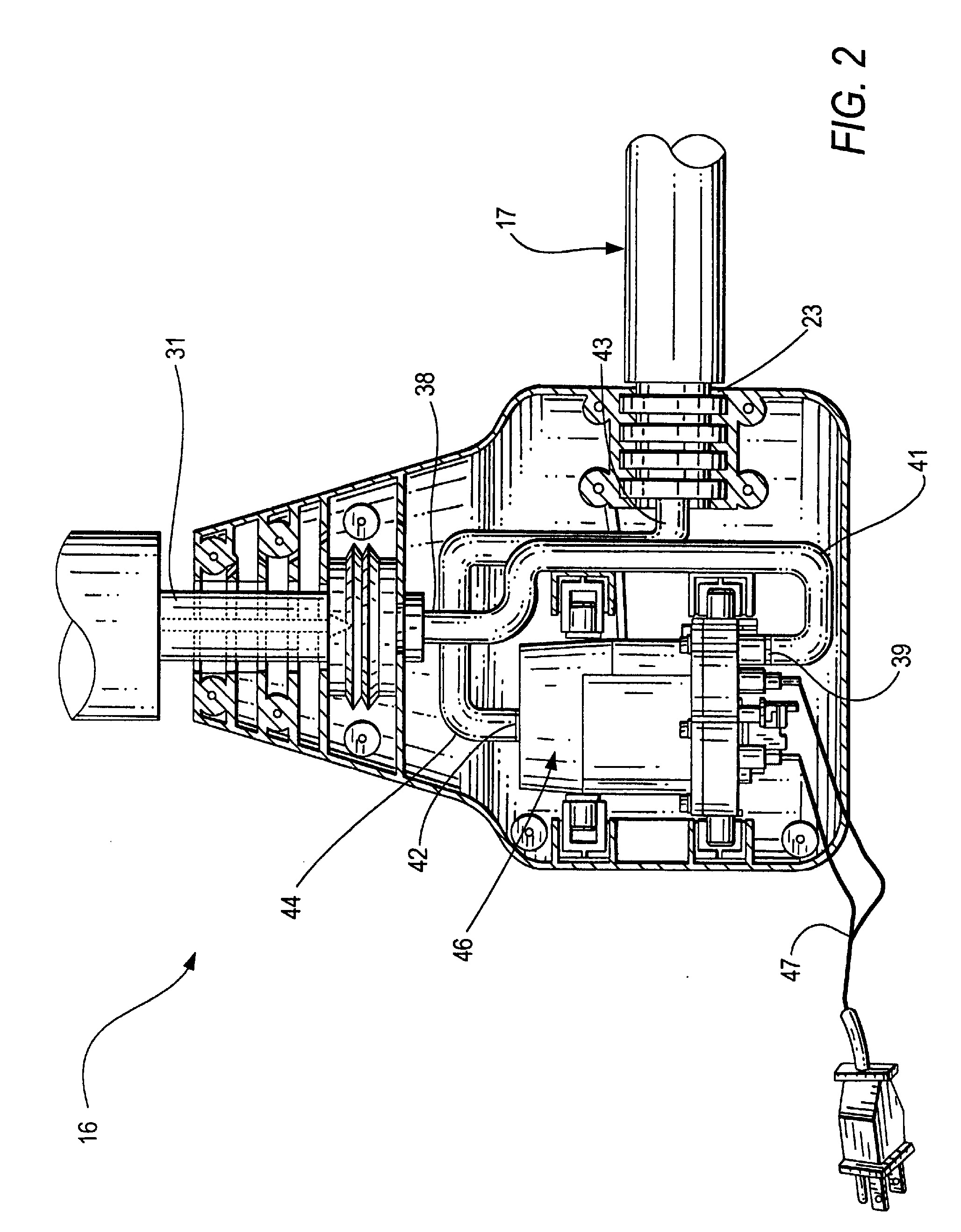
[0007]Generally speaking, in accordance with the invention, a steam mop having a water pump for selectively injecting water from a reservoir to a boiler is provided. The mop includes a housing with an electric boiler and a water pump coupled to a water tank with the pump being actuated by the user's movement to pump water to the boiler for distribution to a steam pocket frame attachment. A fabric steam pocket is mounted on the steam pocket frame to provide a improved cleaning surface.
[0010]In one embodiment, the steam pocket frame is pivotally connected to one side arm for allowing the frame to be flipped over to provide an additional cleaning surface. In another embodiment, there are two side arms also allowing the frame to be flipped over. This allows the mop to be used backward or forwards and is easy to use by right or left handed users.
[0012]Accordingly, it is an object of the invention to provide a steam mop and steam pocket frame attachment to provide increased steam cleaning surface area.
[0014]Another object of the invention is to provide a fabric steam pocket that is easily mounted on a steam pocket frame.

Problems solved by technology

However, conventional mops have not been effective at cleaning dirt in small crevices and floor gaps.
In addition, conventional mops require frequent rising since mops can only effectively clean a small surface area at a time.
This tends to wet the cloth and reduce the cleaning effectiveness of the steam.

Method used


Image

  • Steam mop
  • Steam mop
  • Steam mop

Examples


Embodiment Construction

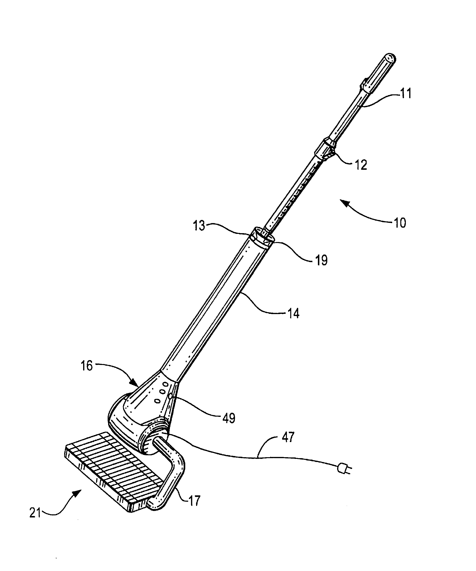
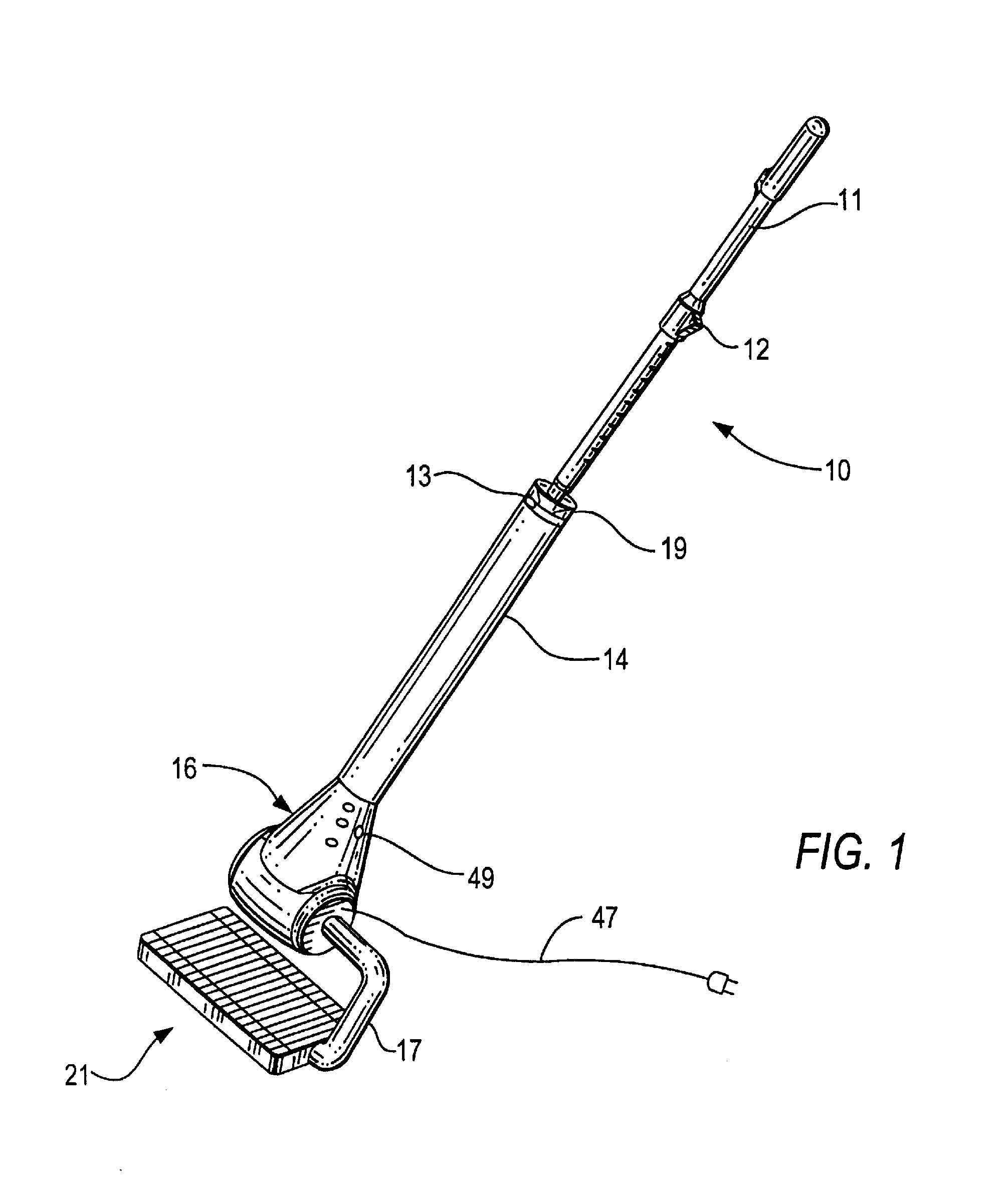
[0034]FIG. 1 is a perspective view of a steam mop 10 constructed and arranged in accordance with one embodiment of the invention. Mop 10 includes a steam pocket frame 21 mounted to a housing or main body 16 by a side arm 17. A water container or tank 14 is mounted to the upper part of housing 16 with a handle 11 and in connected to a boiler 46 by a pump 29 having a one-way outlet valve 37. A water container cover 19 is closed when handle 11 is installed. Water container 14 also has a handle release button 13 for ease of use to easily detach and attach handle 11. Any type of mechanical pump or some other means of transporting the water to the boiler may be used with steam mop 10. Preferably, pump 29 is a mechanical pump, such as a bellows pump or a piston pump, that is actuated by movement of mop 10 by a user pushing and pulling handle 11.

[0035]Steam pocket frame 21 is rectangular in shape and includes a steam inlet coupling 22 at the side end and at the end of side arm 17. Steam gen...


PUM


Abstract

A steam mop having a main body with a boiler, a water container, a mechanical water pump between the boiler and container and at least one side arm connecting the boiler steam outlet to a fabric steam pocket frame. The water pump is actuated by movement of the mop when cleaning to send water to the boiler. The steam pocket frame is substantially rectangular with a plurality of baffles to distribute steam disposed substantially perpendicular to a steam channel having openings to distribute steam between the baffles. A replaceable fabric pocket fits snugly over the frame to distribute cleaning steam to the surface to be cleaned.

Description

BACKGROUND OF THE INVENTION[0001]The invention relates generally to a steam mop, and more particularly to a steam mop including a mechanical water pump that is actuated by the movement of a user to pump water from a water container to a boiler for generating steam to be distributed to a steam pocket applied to a surface to be cleaned.[0002]Conventional mops have been widely used for cleaning floors. However, conventional mops have not been effective at cleaning dirt in small crevices and floor gaps. In addition, conventional mops require frequent rising since mops can only effectively clean a small surface area at a time.[0003]Steaming devices used to apply steam to household objects are well known. The uses of the devices vary widely, and may include the application of steam to drapes or other fabrics to ease wrinkles, and the application of steam to objects to assist in cleaning the objects.[0004]Typical steam devices have a reservoir for storing water that is connected to an elec...

Claims


Application Information

Patent Timeline
Patent Type & Authority Applications(United States)
IPC IPC(8): A47L11/34
CPCA47L13/22A47L13/225A47L13/256F04B43/0063F22B1/28B08B1/00B08B2230/01F04B5/02F22B1/285
Inventor ROSENZWEIG, MAXIMILIANVRDOLJAK, OGNJEN
Owner EURO PRO OPERATING
Learn More