Hydraulic cylinder limiter

Active Publication Date: 2008-10-02
BLUE LEAF I P
View PDF11 Cites 2 Cited by
  • Summary
  • Abstract
  • Description
  • Claims
  • Application Information

AI Technical Summary

Benefits of technology

[0005]Accordingly, it is an object of the present invention to limit the stroke of a hydraulic cylinder such that the vehicle's components do not contact or interfere with nearby hydraulic hoses.
[0006]Another object of the present invention is to make the part's design simple enough for installation with no additional parts, thus eliminating the need for washers, bolts, nuts, and tools.
[0008]Yet another object of the present invention is to eliminate vertical movement of the part after installation.
[0009]It is yet another object of the present invention to eliminate lateral movement of the part after installation.

Problems solved by technology

Off road vehicles occasionally exhibit a deficiency of components rubbing against, and thereby damaging, nearby hydraulic cylinder pressure hoses.
Others have the potential to fall off the cylinder or machines with use, get caught up on other parts, injure the operators, or get caught up in the materials being handled.

Method used


Image

  • Hydraulic cylinder limiter
  • Hydraulic cylinder limiter
  • Hydraulic cylinder limiter

Examples


Embodiment Construction

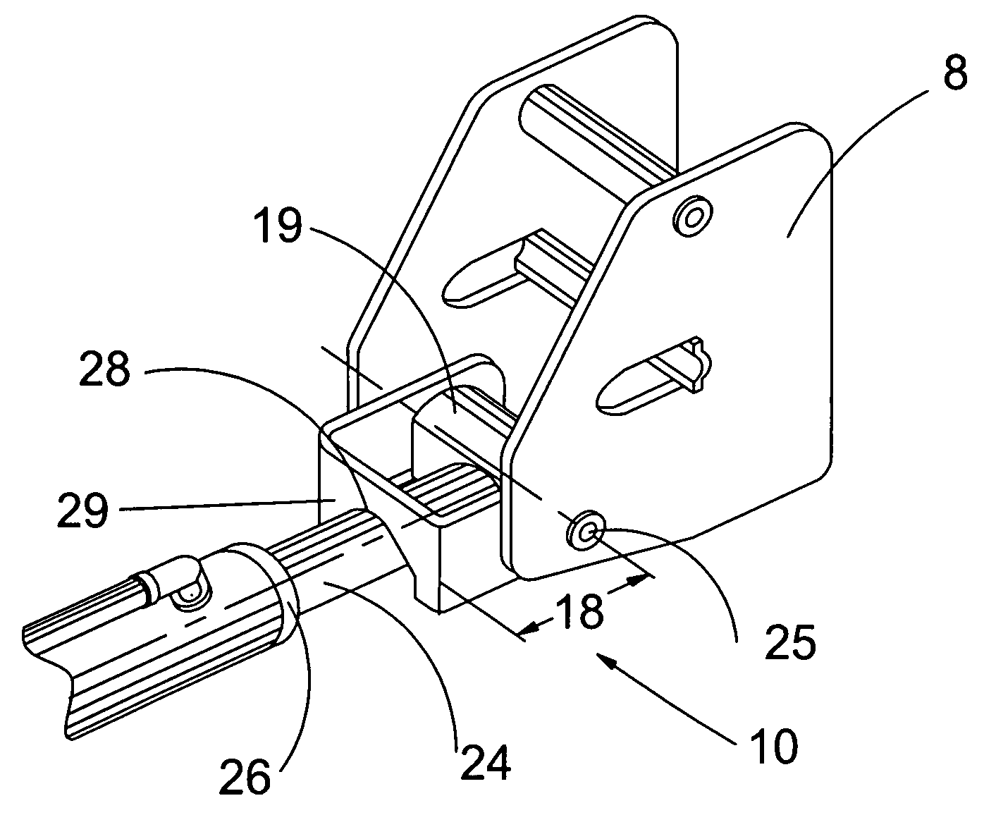
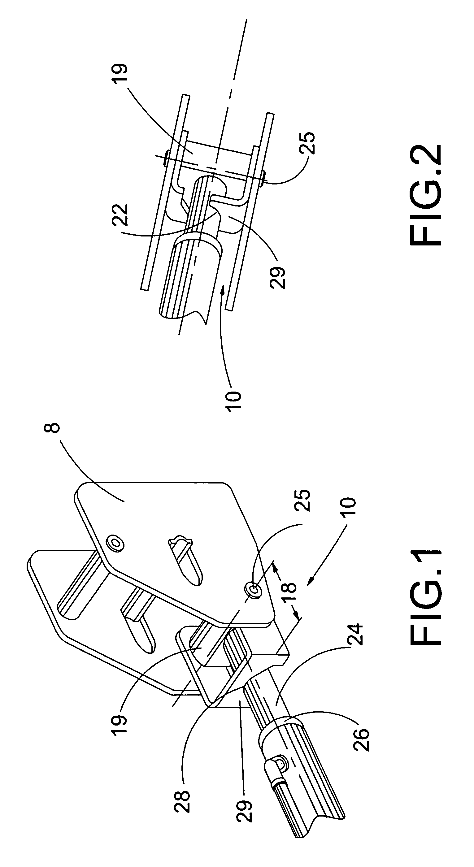
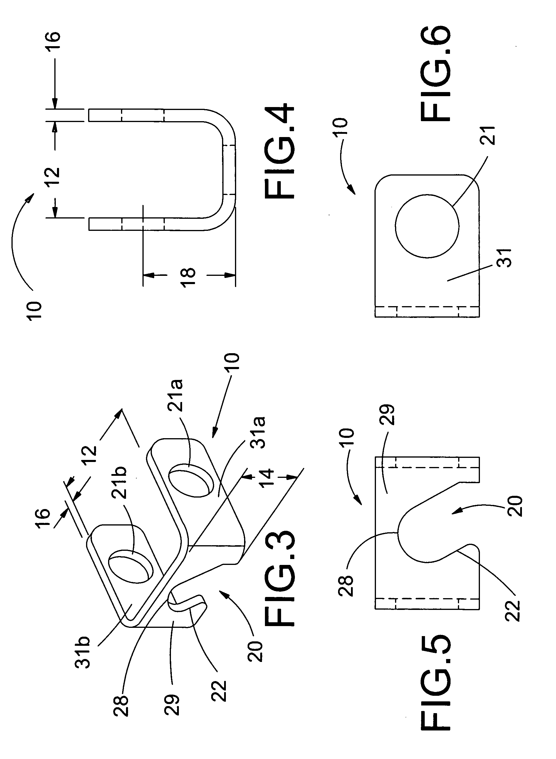
[0021]FIGS. 1-2 show a limiter 10 for a hydraulic cylinder attached to the rod 24 of the cylinder by a pivot pin 25 at the mounting bracket 8. As shown in FIGS. 3-6, the limiter 10 is a U-shaped member having a front base 29 and two side walls 31a, 31b. The base 29 surface of the limiter 10 has a slot 20 which extends from an off center position along the lower edge of the base 29 surface to a semi-circular retention detent 28 located generally in the center of the limiter 10. The side walls 31a, 31b each have aligned attachment holes 21a, 21b through which a pivot pin 25 can be inserted for attaching the limiter 10 to the cylinder end 19. The center points of the attachment holes 21a, 21b are located at generally the same height as the relative center of the retention detent 28.

[0022]The limiter 10 is installed on a hydraulic cylinder by inserting the cylinder rod 24 through the slot 20 and sliding the rod 24 into the retention detent 28 such that the outer circumference of the rod...


PUM


Abstract

A limiter bracket, for restricting the stroke of a hydraulic cylinder, is formed from a U-shaped member having a central base portion and two opposing sidewall. The base has a semi-circular retention slot extending from an off center position centrally located detent within the base. The opening of the slot is asymmetrically located at an off center position along an edge of the base so that the rod of a cylinder is both horizontally and vertically displaced during positioning within the limiter. Once the rod is located in the detent of the limiter, a pivot pin is inserted through a connector at the end of the rod and the aligned attachment holes in the sidewalls securing the limiter to the rod. The end of the cylinder body will contact the base of the limiter during retraction of the rod thus limiting the overall stroke of the cylinder.

Description

CROSS REFERENCE TO RELATED PATENT APPLICATIONS[0001]This applications claims priority to U.S. Provisional Patent Application No. 60 / 469,814 filed on Mar. 28, 2007.[0002]The present invention related to a limiting mechanism for the stroke of a hydraulic cylinder. Off road vehicles occasionally exhibit a deficiency of components rubbing against, and thereby damaging, nearby hydraulic cylinder pressure hoses. Limiting the stroke of the hydraulic cylinders solves this problem by restricting the hoses from the path of nearby components.[0003]There are several varieties of hydraulic cylinder limiters and stops on the market. Some require assembly, multiple parts, or tools to apply them. Others have the potential to fall off the cylinder or machines with use, get caught up on other parts, injure the operators, or get caught up in the materials being handled.[0004]Therefore, there is a need in the art for a device to limit the stroke of a hydraulic cylinder without unnecessary assembly, mul...

Claims


Application Information

Patent Timeline
IPC IPC(8): F16F9/54
CPCB60G13/003B60G2204/128B60G2204/45F16F9/58
Inventor COCKRELL, DAVID G.
Owner BLUE LEAF I P
Why Eureka
Try Eureka