Spring seat and damper disk assembly

a damper disk and spring seat technology, which is applied in the direction of shock absorbers, machine supports, mechanical equipment, etc., can solve the problems of sliding components being subjected to a large load to the outside, sliding components are subjected to a large load, and friction resistance diminishes the ability of the damper disk assembly to dampen torsional vibration, etc., to achieve better torsional vibration attenuation and increase stiffness

Active Publication Date: 2008-10-02
NISSAN MOTOR CO LTD +1
View PDF17 Cites 11 Cited by
  • Summary
  • Abstract
  • Description
  • Claims
  • Application Information

AI Technical Summary

Benefits of technology

[0026]Stiffness can be increased with the spring seat pertaining to the present invention.
[0027]Better torsional vibration attenuation can be achieved with the damper disk assembly pertaining to the present invention.

Problems solved by technology

When the input and output rotors rotate relative to each other, the coil springs are compressed in the rotational direction between the two rotors, which causes the torsional vibration inputted to the input rotor to be absorbed and dampened.
This frictional resistance diminishes the ability of the damper disk assembly to dampen torsional vibration.
If a spring seat has relatively low stiffness, however, when the coil springs are subjected to a strong centrifugal force, the sliding component is subjected to a large load to the outside in the radial direction, and the sliding component elastically deforms to the outside in the radial direction.
This frictional resistance can bring about a decrease in the ability of the damper disk assembly to dampen torsional vibration.
That is, if the stiffness of the spring seats is low, there is the risk that the ability of the damper disk assembly to dampen torsional vibration will be diminished.

Method used


Image

  • Spring seat and damper disk assembly
  • Spring seat and damper disk assembly
  • Spring seat and damper disk assembly

Examples


Embodiment Construction

[0039]Selected embodiments of the present invention will now be explained with reference to the drawings. It will be apparent to those skilled in the art from this disclosure that the following descriptions of the embodiments of the present invention are provided for illustration only and not for the purpose of limiting the invention as defined by the appended claims and their equivalents.

Configuration of Damper Disk Assembly

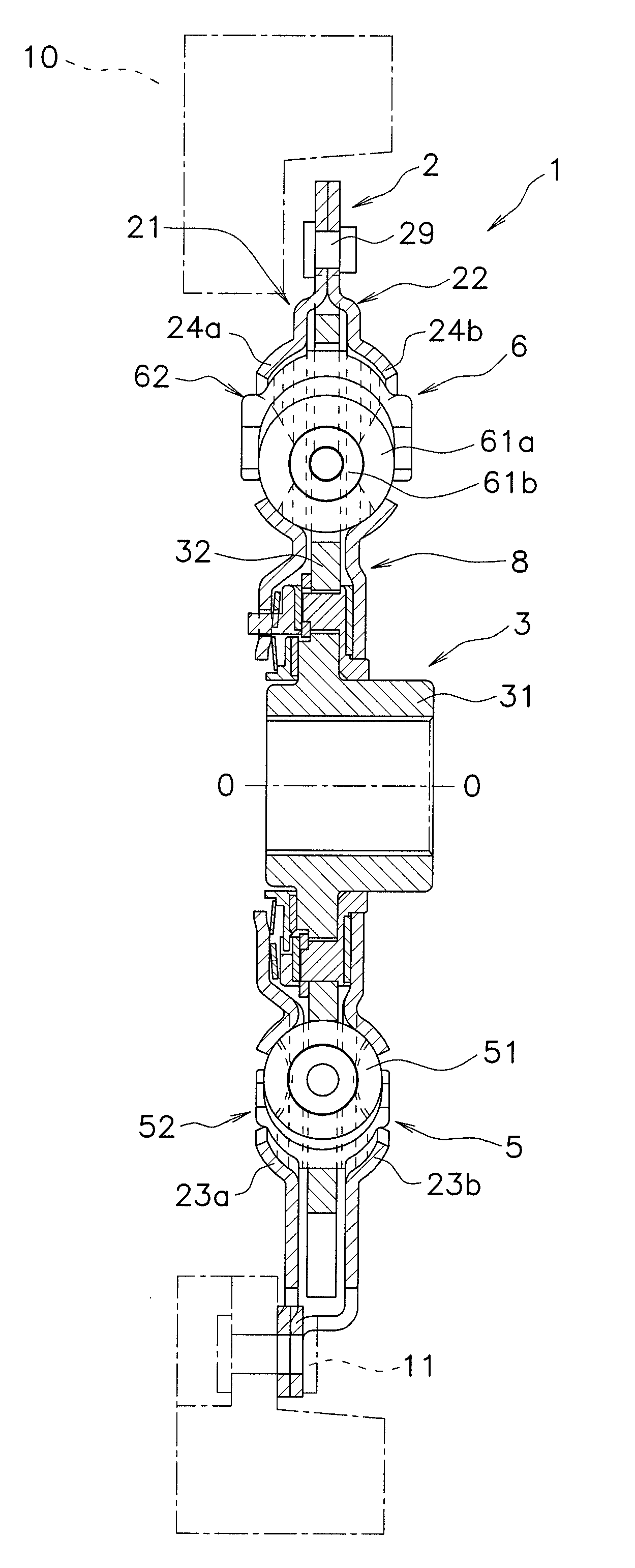
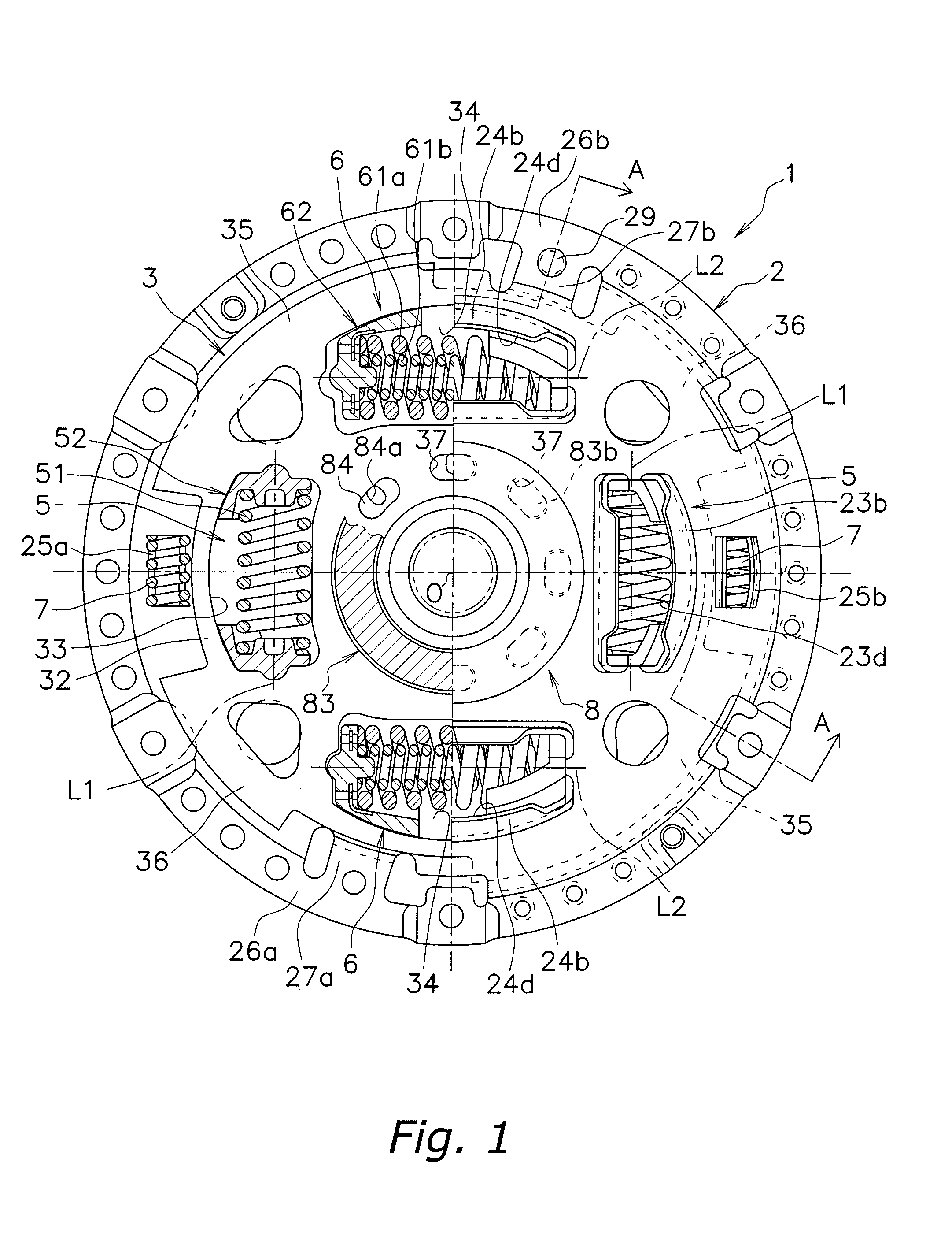
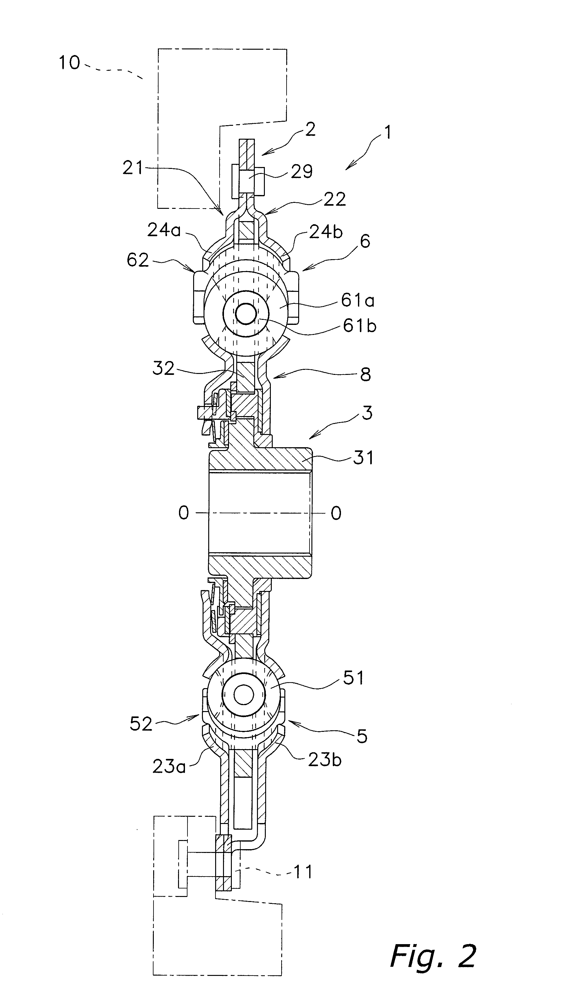
[0040]The configuration of the damper disk assembly 1 according to a preferred embodiment of the present invention will be described with reference to FIGS. 1 to 4. FIG. 1 is a simplified elevational view of the damper disk assembly 1. FIG. 2 is a simplified vertical cross-sectional view of the damper disk assembly 1 taken along the line A-A in FIG. 1. FIGS. 3 and 4 are partial cross-sectional views of the damper disk assembly 1. FIG. 1 shows a neutral state in which no torque is inputted to the damper disk assembly 1.

[0041]In the following description, the term...


PUM


Abstract

Second spring seats 62 each have a first support component 63, a second support component 64, and a reinforcing plate 66. The first support component 63 supports the ends of second coil spring 61a in the rotational direction. The second support component 64 extends in the rotational direction from the first support component 63 and supports the end of the second spring 61a in the radial direction. At least part of the reinforcing plate 66 is embedded in at least one of the first and second support components 63 and 64. The reinforcing plate 66 directly or indirectly supports the end of the second spring 61a along with the first and second support components 63 and 64.

Description

CROSS-REFERENCE TO RELATED APPLICATIONS[0001]This application claims priority to Japanese Patent Application No. 2007-090389 filed on Mar. 30, 2007. The entire disclosure of Japanese Patent Application No. 2007-090389 is hereby incorporated herein by reference.BACKGROUND OF THE INVENTION[0002]1. Field of the Invention[0003]The present invention relates to a spring seat and a damper disk assembly, and more particularly relates to a spring seat that supports a spring that absorbs and dampens torsional vibration.[0004]2. Background Information[0005]To transmit the power generated by an engine, a vehicle is equipped with power transmission devices such as a clutch disk assembly, a flywheel assembly, and a torque converter lock-up apparatus. These power transmission devices are provided with a damper disk assembly that absorbs and dampens torsional vibrations and the like.[0006]This kind of damper disk assembly main includes an input rotor, an output rotor, and a plurality of coil spring...

Claims


Application Information

Patent Timeline
Patent Type & Authority Applications(United States)
IPC IPC(8): F16D65/14F16F15/00
CPCF16F15/12326F16F15/12346
Inventor OONO, AKIHIKOASAI, SOUICHIMASAKI, MICHITOMOHARADA, TAKASHI
Owner NISSAN MOTOR CO LTD
Why Eureka
Try Eureka