
Arrangement For Fixing the Gas Generator of an Air Bag Unit

a gas generator and air bag technology, applied in the direction of vehicle safety arrangments, couplings, pedestrian/occupant safety arrangements, etc., can solve the problems of affecting the safety of passengers, and not being certain that the arrangement guarantees the necessary mechanical stability, etc., to achieve the effect of reliable sealing of the generator housing against the environmen

Inactive Publication Date: 2008-10-02
ZF FRIEDRICHSHAFEN AG
View PDF6 Cites 8 Cited by
  • Summary
  • Abstract
  • Description
  • Claims
  • Application Information

AI Technical Summary

Benefits of technology

[0006]The object of the present invention is to provide a solution, by means of which a gas generator can be securely fixed in the generator chamber, and both radial and axial tolerances, in particular of the gas generator, can be compensated. At the same time, a reliable sealing of the generator housing against the environment shall be achieved.
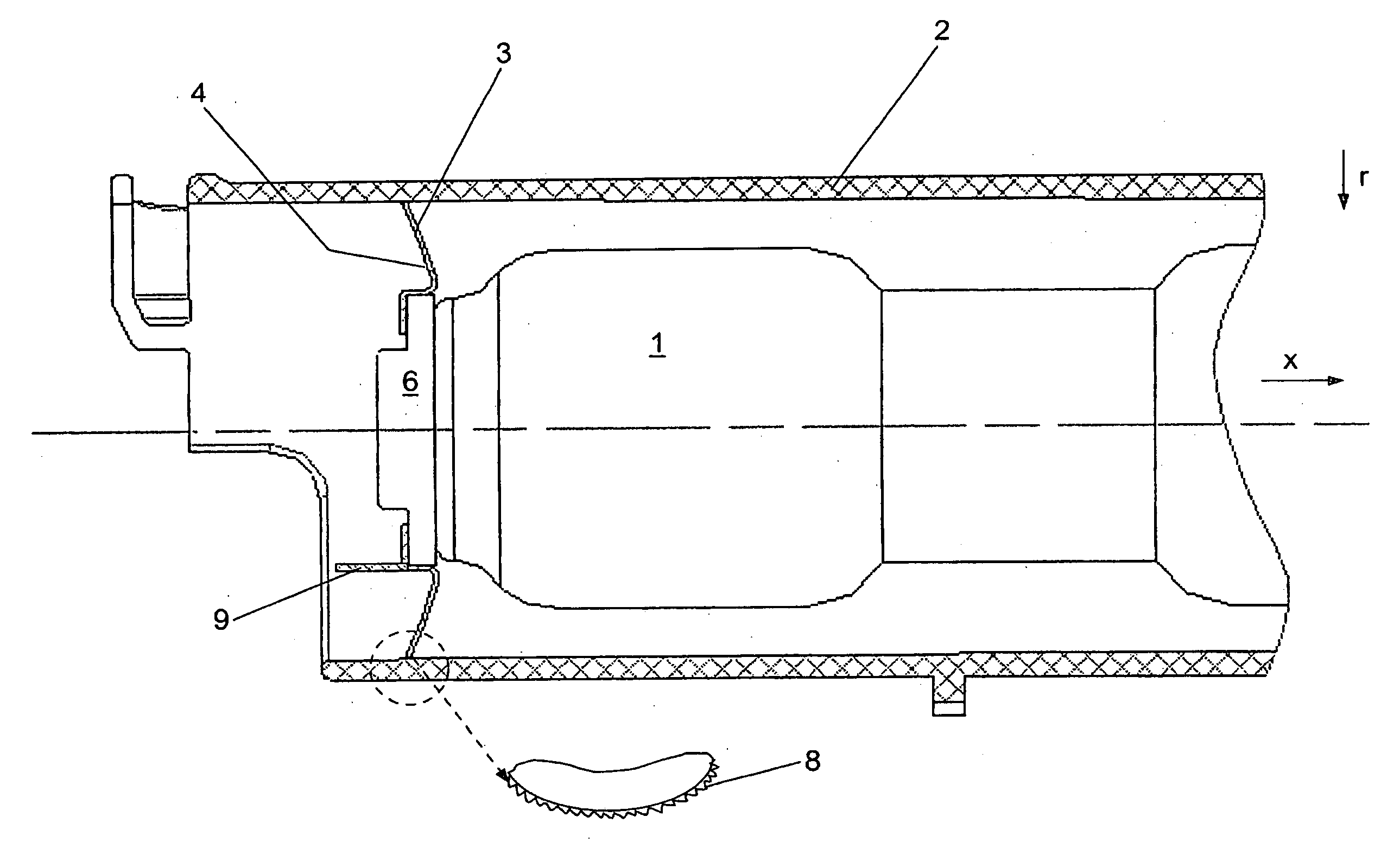
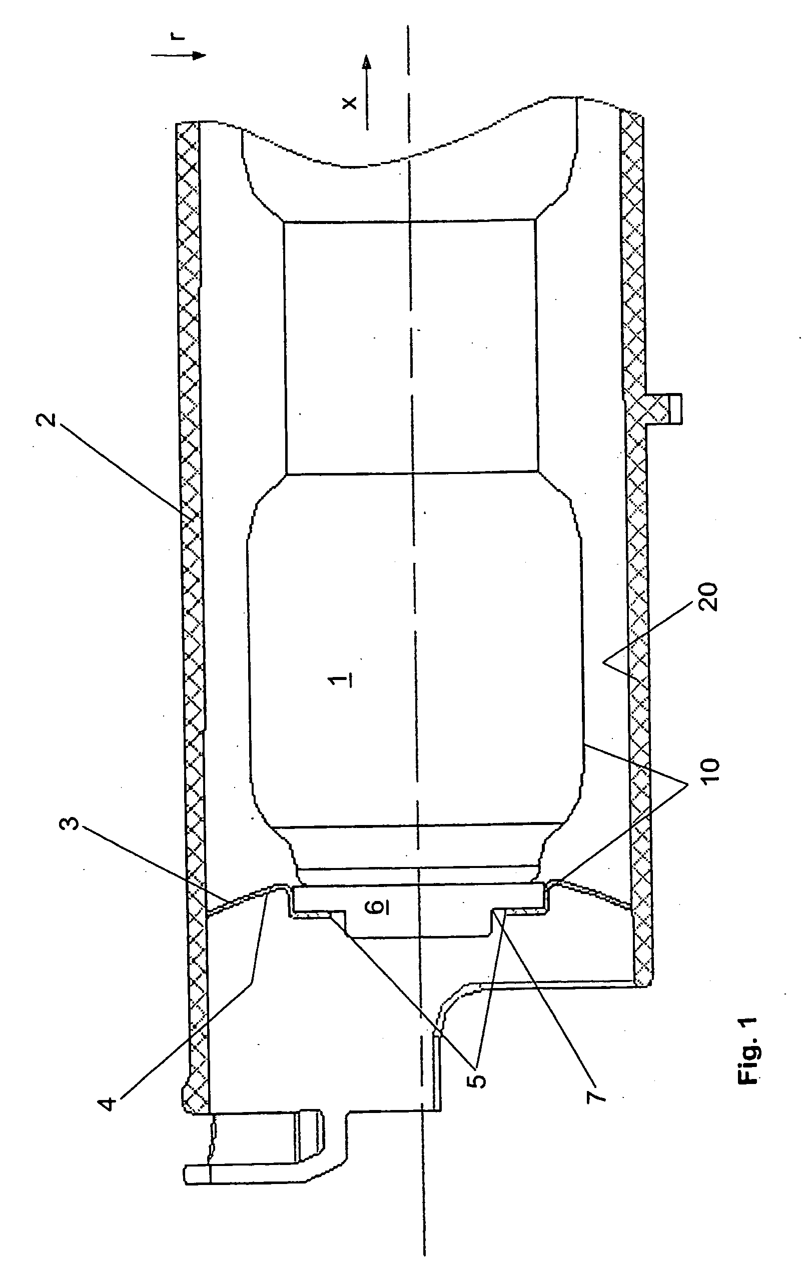
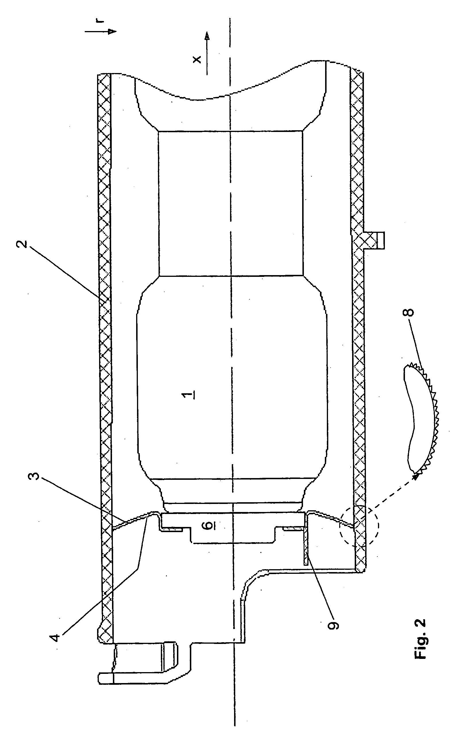
[0009]A reliable fixing of the gas generator in the generator chamber is achieved with the arrangement embodied in the manner described. Both the radial manufacturing tolerances of the gas generator or of the gas generator jacket and / or of the generator chamber and axial tolerances of the gas generator can be compensated without any problems by means of pressing on the plate-like fastening element, since the fastening element is quasi-automatically pushed open so wide during the pressing that it is arranged in a positive lock on the generator outer surface and clings to the inner surface of the generator chamber. Possible axial tolerances are compensated simply via the press-in depth of the fastening element. Moreover, it is particularly advantageous that during the pressing, the fastening element is arched into the interior of the generator chamber in a radial section between the generator outer wall and the chamber inner wall, such that the gas generator is fixed in the generator chamber with a predetermined pretension. This is particularly an advantage with regard to the achieved sealing of the generator chamber, since, when the air bag is triggered, i.e., in case of the escape of gas from the gas generator and an increase in the internal pressure in the generator chamber connected therewith, the arching of the fastening element is pressed in the outward direction, and the fastening element, which consequently increasingly straightens as well as increases slightly in its diameter, clings even more rigidly to the chamber inner wall.
[0013]As a variant of this, it is, however, also possible to make the fastening element out of a composite material and to manufacture it, for example, out of a sheet steel, which is extrusion-coated about the inner lug of the fastening element and on the inner contour thereof with a plastic. Consequently, by means of a corresponding choice of the materials, the sealing behavior in the area of the generator bottom can, if necessary, still be improved, since the generator bottom is pressed into the plastic surrounding the inner lug during the pressing of the fastening element. According to a particularly advantageous embodiment of this variant, the fastening element can, moreover, be snapped onto the gas generator with its inner lug. As a result, it can already be premounted at the gas generator and inserted together with same into the generator chamber during the assembly of the air bag unit and pressed between the gas generator and the generator chamber.

Problems solved by technology

With the increasing number of air bag units installed in a vehicle, these represent a cost factor that is of increasing consequence.
However, provided that additional sealing measures are not taken in the area of the flange, leakage problems may possibly occur with this solution in view of the frictionally engaged press fit of the gas generator and adapter.
Also, it does not appear to be certain that the arrangement guarantees the necessary mechanical stability over the longer term in case of the stress occurring in practice.
Consequently, the axial fixing of the gas generator is achieved; however, the geometry of the sealing and uncoupling ring becomes more complicated.
Moreover, tolerances of the axial measurements of the gas generator cannot or can hardly be compensated with this solution.

Method used


Image

  • Arrangement For Fixing the Gas Generator of an Air Bag Unit
  • Arrangement For Fixing the Gas Generator of an Air Bag Unit
  • Arrangement For Fixing the Gas Generator of an Air Bag Unit

Examples


Embodiment Construction

[0019]Referring to the drawings in particular, FIG. 1 shows the present invention in a schematic view according to a basic embodiment. The figure concerns only the cutaway portion of an air bag unit which is otherwise not further explained. FIG. 1 shows a part of the generator chamber housing 2 with the gas generator 1, likewise shown only partially, arranged therein. The remaining components of the air bag unit, whose design is well known, are not shown in the drawing. The diffuser, which is likewise not shown in this respect, which provides for a distribution of the gas stream for an inflation of the air bag that is as uniform as possible, can be embodied either at the generator 1 itself and / or by a corresponding profiled section of the inner wall of the generator housing 2.

[0020]In the example shown, the gas generator 1 is embodied as an almost cylindrical part that is essentially rotationally symmetrical in relation to the longitudinal axis or the axial direction x. At its one a...


PUM


Abstract

An arrangement for fixing a gas generator of an air bag unit. The gas generator is securely fixed in the generator chamber and both radial and axial tolerances, in particular of the gas generator, are compensated using a plate-like, spring-elastic fastening element that is pressed in the area of the end of the gas generator lying opposite the fixed bearing between the outer circumference thereof and the inner circumference of the generator chamber axially projecting through the gas generator. After the pressing in, the fastening element is arched into the generator chamber in the axial direction in a section between the outer wall of the gas generator and the inner wall of the generator chamber in the axial direction.

Description

CROSS REFERENCE TO RELATED APPLICATIONS[0001]This application is a United States National Phase application of International Application PCT / DE2005 / 000336 and claims the benefit of priority under 35 U.S.C. § 119 of German Patent Application DE 10 2004 010 144.2 filed Feb. 27, 2004, the entire contents of which are incorporated herein by reference.FIELD OF THE INVENTION[0002]The present invention pertains to an arrangement for fixing the gas generator of an air bag unit, and in particular for fixing the gas generator in the generator chamber and for sealing the generator chamber against the environment. The present invention pertains to an air bag unit of typical design with an air bag housing, to which an air bag is fixed, and with a generator chamber connected to the air bag housing, which generator chamber accommodates the gas generator for releasing a gas that fills the air bag in case of a collision.BACKGROUND OF THE INVENTION[0003]Air bag units with the basically above-describe...

Claims


Application Information

Patent Timeline
Patent Type & Authority Applications(United States)
IPC IPC(8): B60R21/16B60R21/20B60R21/217
CPCB60R21/2171Y10T24/44248Y10T403/405B60R2021/2175
Inventor WAGENER, KEITFANGMANN, THOMAS
Owner ZF FRIEDRICHSHAFEN AG
Learn More