
Heater system for an aircraft seat

Active Publication Date: 2008-10-02
BE AEROSPACE INCORPORATED +1
View PDF27 Cites 22 Cited by
  • Summary
  • Abstract
  • Description
  • Claims
  • Application Information

AI Technical Summary

Benefits of technology

[0008]In one implementation of a heater system provided for a seat in an aircraft, the seat has a bottom cushion and a back cushion, both having an upholstery cover. The heater system includes a first heater pad integrated into the bottom cushion under the upholstery cover, and a second heater pad integrated into the back cushion under the upholstery cover. Each of the first and second heater pads comprises a body of a material that is self flame extinguishing, and an electric resistance wire carried by the body.
[0009]Preferably, each heater pad is formed by a carrier of open cell foam material with a surface on which the electric resistance wire is arranged in a pattern. Although various patterns may be used, in one form, the electric resistance wire is arranged in a plurality of rows, each having a serpentine or winding pattern, for example. An outer foam layer may be adhered to the surface of the carrier to embed the electric resistance wire with in the heater p

Problems solved by technology

Although the cabin usually is heated to room temperature before the passengers board, the seats often do not reach a comfortable temperature by boarding time.
Seats on executive aircraft often are covered in leather, which is well known for being uncomfortable when cold.
Incorporating seat heaters into aircraft seats presents additional challenges that do not exist with automobile seat heaters.
Lightning frequently strikes aircraft and damage electronic devices Therefore many factors have to be considered when providing an aircraft seat heater system that do not have to be considered for automobile seat heaters.

Method used


Image

  • Heater system for an aircraft seat
  • Heater system for an aircraft seat
  • Heater system for an aircraft seat

Examples


Embodiment Construction

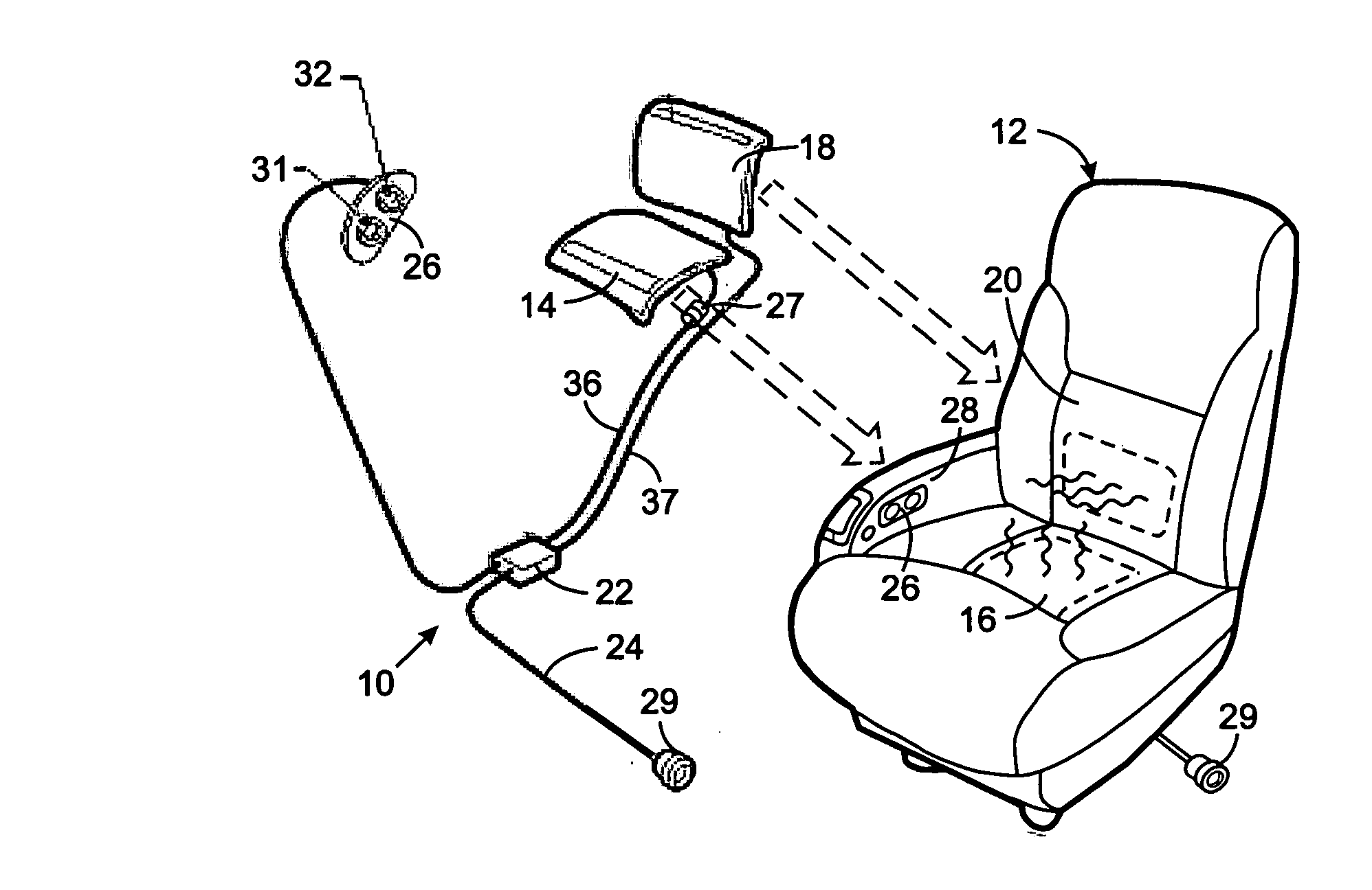
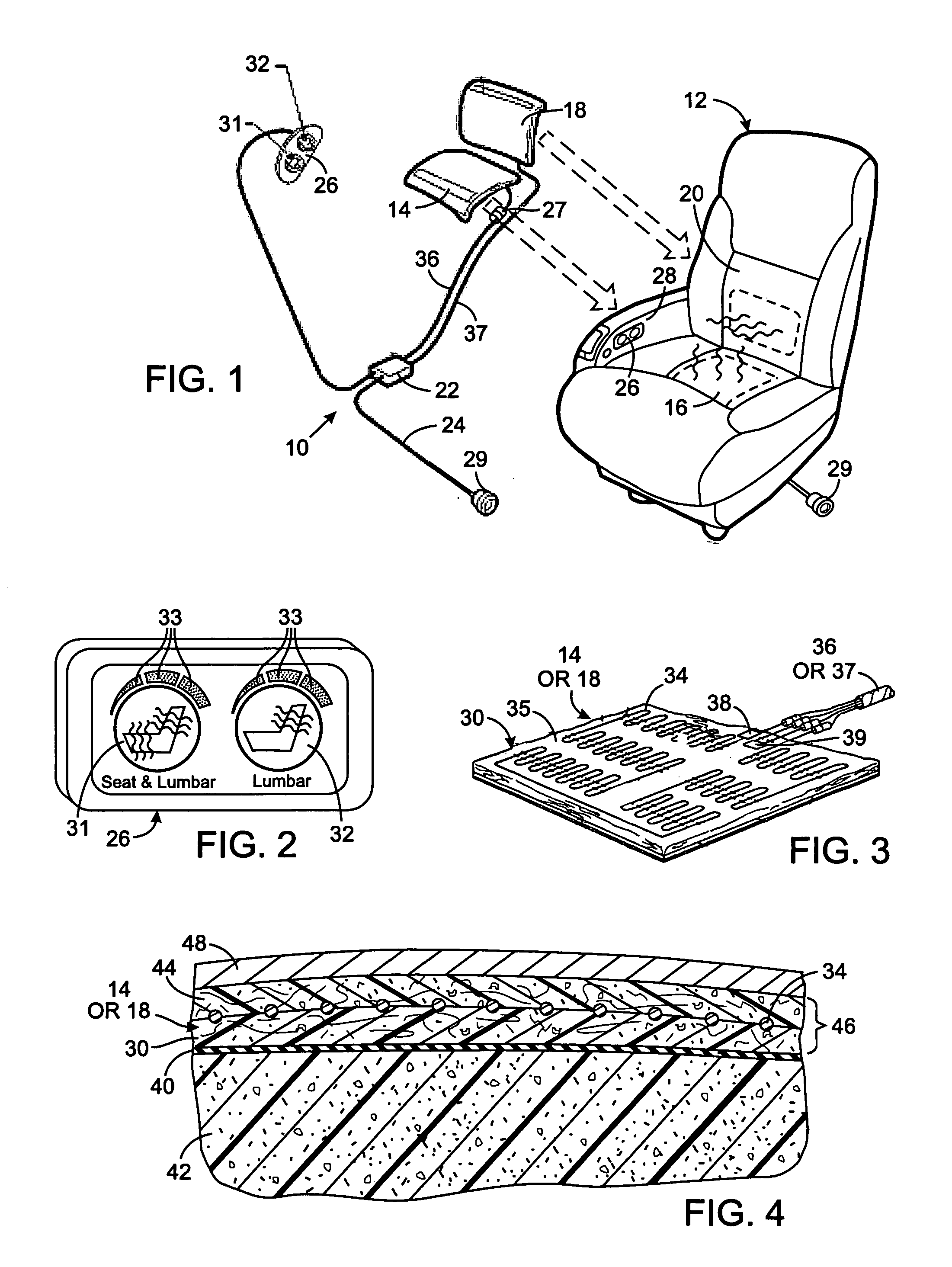
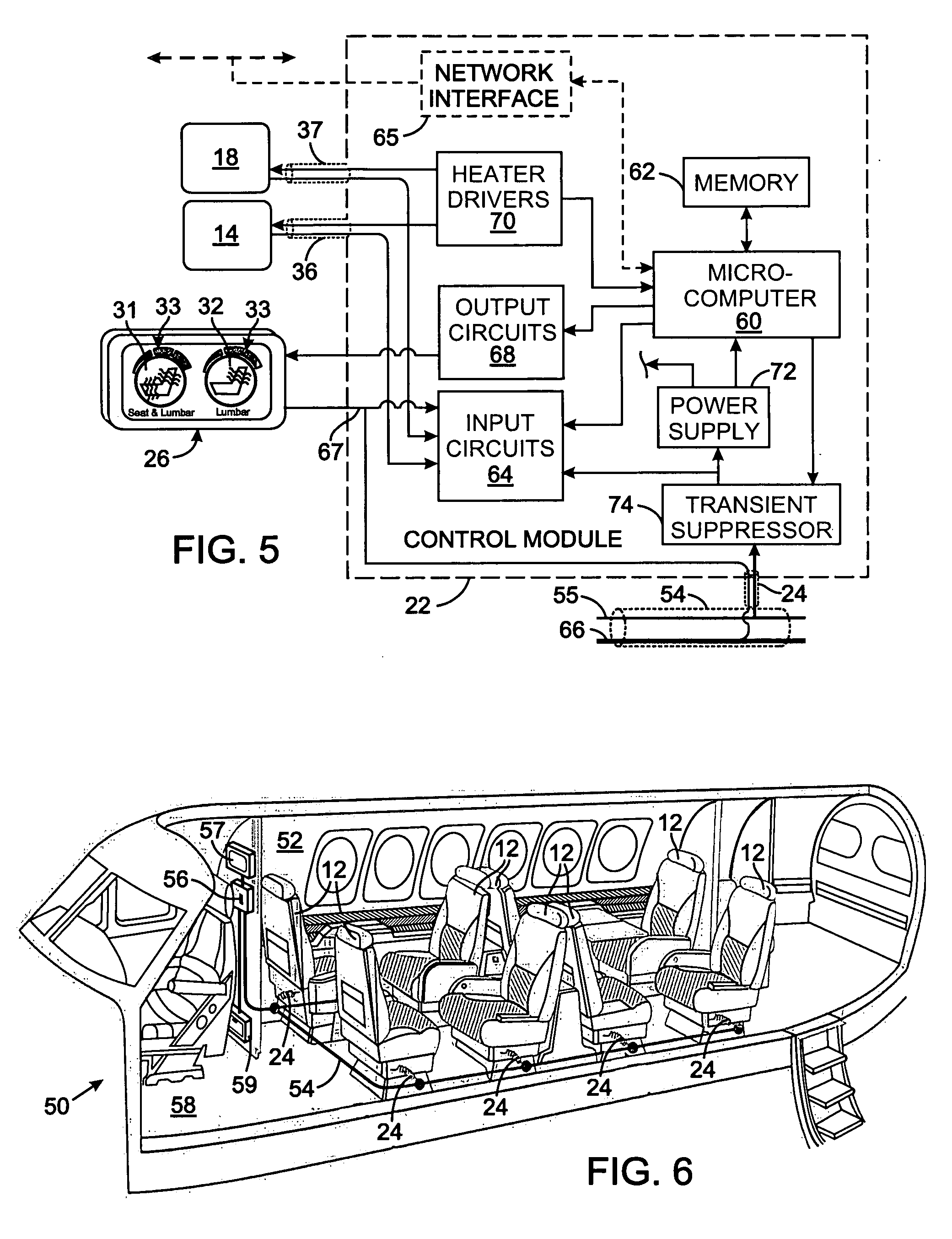
[0018]With initial reference to FIG. 1, one implementation of a seat heater system 10 for an aircraft passenger seat 12 comprises a first heater pad 14 for the seat bottom cushion 16 and a second heater pad 18 for the seat back cushion 20. The first and second heater pads 14 and 18 receive direct current (DC) power from a control module 22, that is beneath the seat and connected by a power cable 24 to the electrical system of the aircraft. Alternatively, when two or more seats are adjacent each other, a single control module can govern operation of the heater pads in those seats. The amount of electricity applied to each of the heater pads 14 and 18 by the control module 22, and thus the level of heat, is determined in response to activation of a switch module 26 located in an arm rest 28 of the passenger seat 12. The control module 22 cycles the first and second heater pads 14 and 18 on and off at different intervals depending on the level of heat desired by the seat occupant. Circ...


PUM


Abstract

A heater system for an aircraft seat includes a first heater pad secured to the bottom seat cushion and a second heater pad secured to the back seat cushion, with both pads being under an upholstery cover. The first and second heater pads each has a body of an open cell foam material that is self flame extinguishing, and an electric resistance wire embedded in a winding pattern within the body. A control module applies a variable electric current to the electric resistance wire in each of the first and second heater pads. Preferably only the second heater pad for the back seat cushion can be activated or both the first and second heater pads can be activated. A pushbutton switch module allows the seat occupant step the control module through a sequence of different heating levels.

Description

CROSS-REFERENCE TO RELATED APPLICATIONS[0001]This application claims benefit of U.S. Provisional Patent Application No. 60 / 896,944 filed on Mar. 26, 2007.STATEMENT REGARDING FEDERALLY SPONSORED RESEARCH OR DEVELOPMENT[0002]Not ApplicableBACKGROUND OF THE INVENTION[0003]1. Field of the Invention The present invention relates to heaters for seats, and more particularly to heater systems for aircraft seats.[0004]2. Description of the Related Art[0005]Between flights, aircraft frequently sit outdoors for prolonged periods of time, such as overnight. During such periods in winter, the temperature of the aircraft cabin decreases well below levels that are considered comfortable to passengers. Although the cabin usually is heated to room temperature before the passengers board, the seats often do not reach a comfortable temperature by boarding time. Seats on executive aircraft often are covered in leather, which is well known for being uncomfortable when cold. In addition, the application ...

Claims


Application Information

Patent Timeline
IPC IPC(8): B60N2/56H02H3/22
CPCB60N2/5685B64D11/0647B64D11/0626B64D11/06B64D11/0624
Inventor PARNIS, WILLIAM R.CASSAVANT, COREY S.STUEF, THOMAS A.
Owner BE AEROSPACE INCORPORATED
Features
  • Generate Ideas
  • Intellectual Property
  • Life Sciences
  • Materials
  • Tech Scout
  • Unparalleled Data Quality
  • Higher Quality Content
  • 60% Fewer Hallucinations
Learn More