Energy recycle system for use with ac current power supply

a technology of energy recycling and ac current, which is applied in the direction of emergency power supply arrangements, instruments, pulse techniques, etc., can solve the problems of additional energy waste in the air-conditioning system, additional energy consumption dissipated by the air-conditioning system,

Active Publication Date: 2008-10-02
DELTA ELECTRONICS INC
View PDF6 Cites 11 Cited by
  • Summary
  • Abstract
  • Description
  • Claims
  • Application Information

AI Technical Summary

Problems solved by technology

In this case, a large amount of energy is transformed into heat and dissipated thereby, which causes additional energy consumption dissipated by the air-conditioning system.
Under this condition, a large amount of energy is converted into heat and dissipated thereby, which would cause additional energy waste in the air-conditioning system.

Method used


Image

  • Energy recycle system for use with ac current power supply
  • Energy recycle system for use with ac current power supply
  • Energy recycle system for use with ac current power supply

Examples


first embodiment

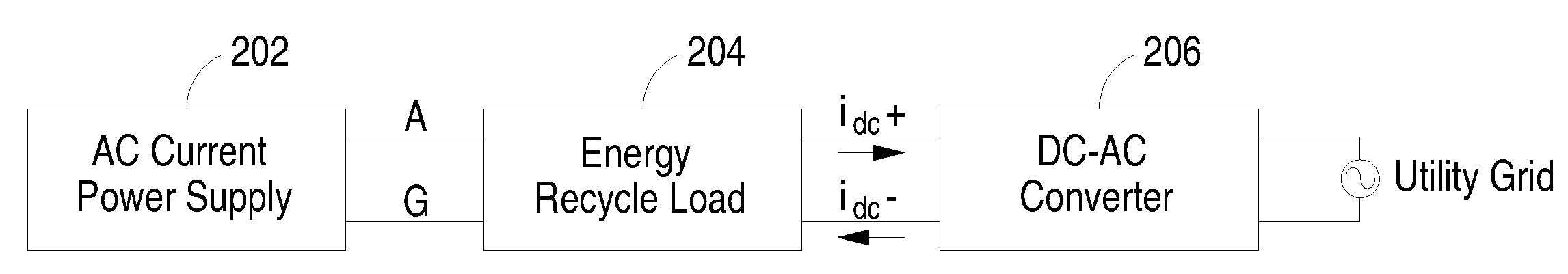
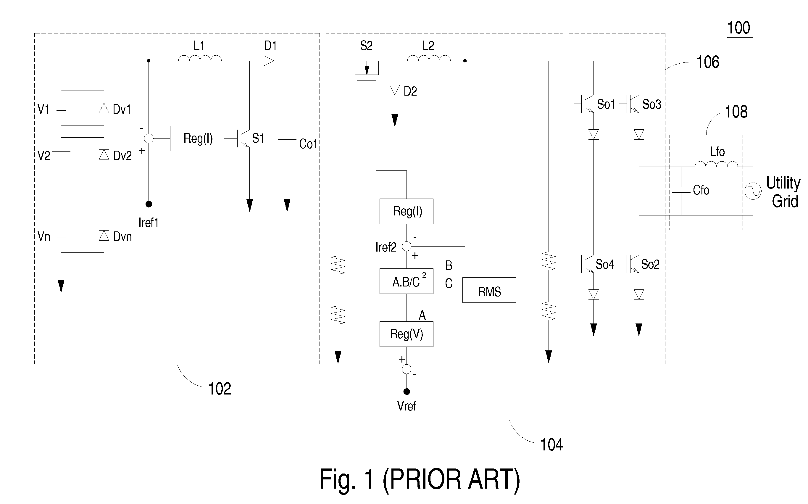
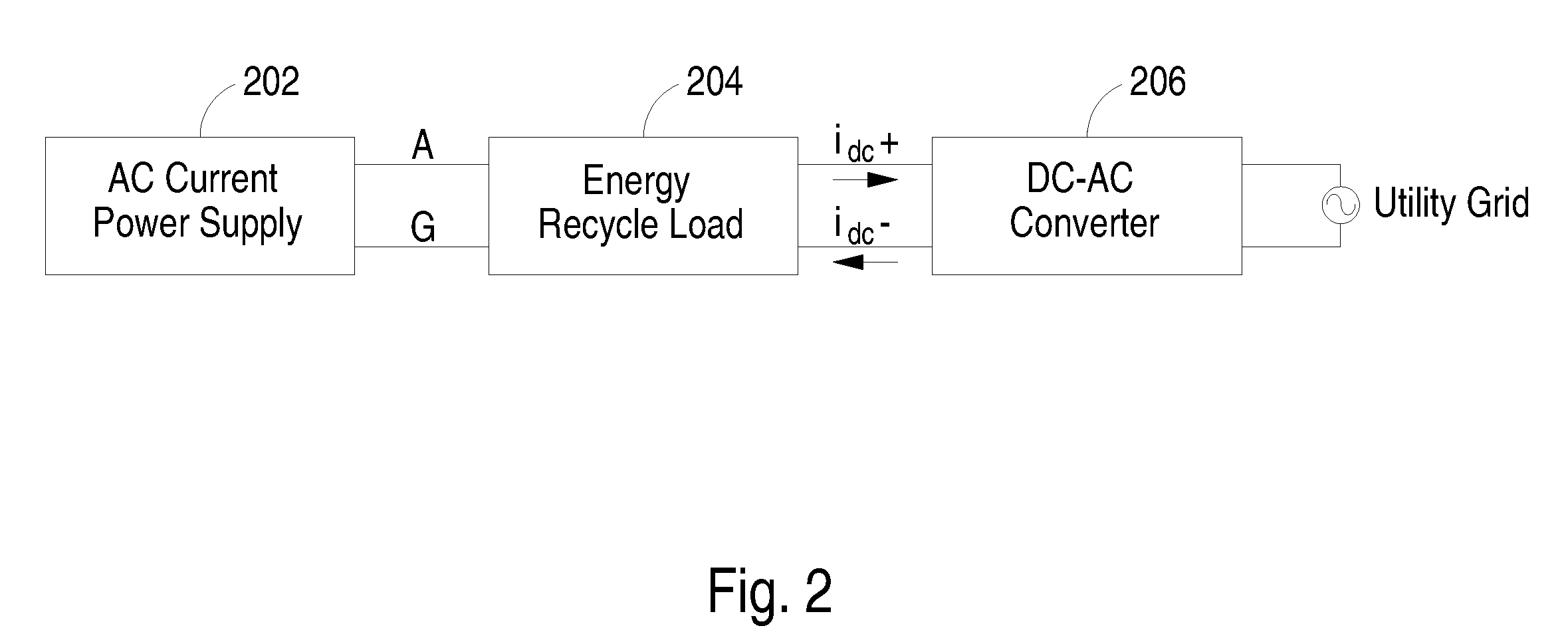
[0025]FIG. 2 shows a systematic block diagram of an AC current power supply and an energy recycle system thereof according to the present invention. The AC current power supply 202 is configured to output an AC current, which is provided to an energy recycle load 204. The energy recycle load 204 is configured to draw an AC load current from the AC current power supply 202 and convert the AC current into a DC current idc. Besides, an energy recycle converter circuit such as a DC-AC converter 206 is connected in series with the energy recycle load 204 and configured to convert the output DC current idc and the output DC voltage of the energy recycle load 204 into an AC current or an AC voltage, so as to deliver the energy back to the utility grid. The energy recycle converter circuit can be implemented by a variety of converter topologies, such as a series circuit consisted of a buck converter 104 and a DC-AC converter of FIG. 1. Certainly, the energy recycle converter circuit can als...

second embodiment

[0030]FIG. 7 illustrates the example where the energy recycle system is extensively applied to a parallel operation AC current power supply system according to the present invention. As shown in FIG. 7, a plurality of AC current power supplies 202 are parallel operated with each other and each AC current power supply is connected in series with an energy recycle load. The energy recycle loads 204 are configured to convert the output AC current of the AC current power supply system 202 into a DC current, and the energy of the DC current is delivered to the utility grid through the DC-AC converter 206. The output terminals of the energy recycle loads 204 are connected in parallel with each other and together connected to the DC-AC converter 206.

[0031]FIG. 8 illustrates a modified circuit configuration of the energy recycle load. Compared with FIG. 3, the filter 504 of the energy recycle load 204 of FIG. 8 includes a reverse current protection device connected between the filtering ind...


PUM


Abstract

An energy recycle system for use with an AC current power supply, for example, an electronic ballast, is presented. The energy recycle system includes an energy recycle load connected to an output terminal of the AC current power supply, in which the energy recycle load includes a rectifier for rectifying the output AC current of the AC current power supply into a rectified DC current and a filter connected to the rectifier for removing the high-frequency harmonics from the rectified DC current. Also, the energy recycle system further includes a DC-AC converter connected to the energy recycle load for receiving the DC current outputted from the energy recycle load, which is in turn delivered to the utility grid to achieve energy recycling.

Description

FIELD OF THE INVENTION[0001]The present invention is related to an AC current power supply, and more particularly to an energy recycle system for use with an AC current power supply.BACKGROUND OF THE INVENTION[0002]Nowadays, more and more concern is focused on energy recycle for the sake of energy saving and environment protecting. Before a set of products are put on the market, they should experience lots of tests e.g. burn-in test so as to verify that the power parameters are within the specified tolerances with a minimal consumption of electric power by the power supply.[0003]Generally speaking, a power supply has to undergo burn-in test for several hours to verify its reliability and stability. Conventional burn-in test system for power supply uses a resistor tank as the load. In this case, a large amount of energy is transformed into heat and dissipated thereby, which causes additional energy consumption dissipated by the air-conditioning system. In order to save energy consump...

Claims


Application Information

Patent Timeline
Patent Type & Authority Applications(United States)
IPC IPC(8): H02J3/46H02M5/40
CPCH02J3/38H02J9/06
Inventor YAN, CHAOZHENG, CHONGFENGZHAN, ZHIQIANGZENG, JIANHONGYING, JIANPING
Owner DELTA ELECTRONICS INC
Why Eureka
Try Eureka