
Display device

Active Publication Date: 2008-10-02
DENSO CORP
View PDF0 Cites 16 Cited by
  • Summary
  • Abstract
  • Description
  • Claims
  • Application Information

AI Technical Summary

Benefits of technology

[0005]The present invention is made in view of the foregoing matter and it is an object of the present invention to provide a display device which is capable of increasing the recognizability of an indication point indicated by a pointer image. It is another object of the present invention to provide a display device which is capable of increasing the recognizability of motion of the pointer image.
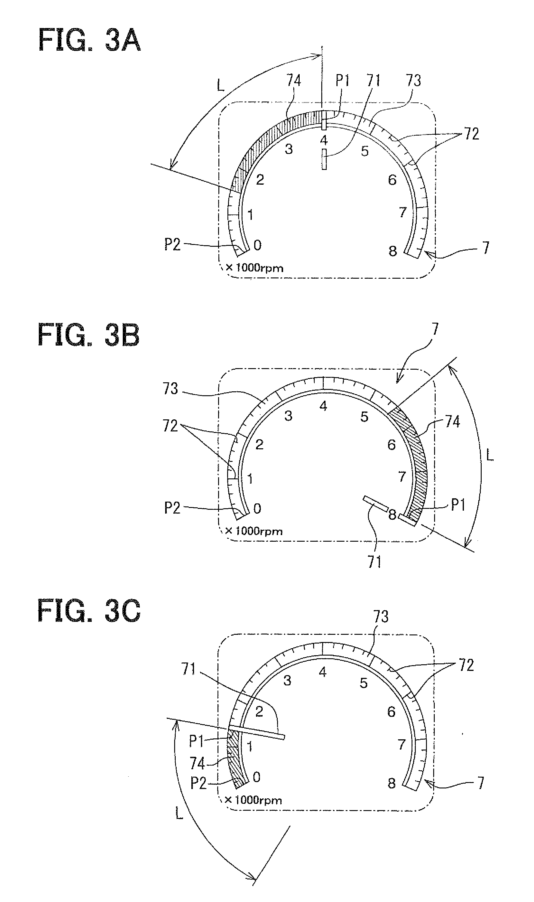
[0007]Accordingly, the motion of the pointer image is highlighted by the highlight image. Further, an indication position of the pointer image is accentuated by the highlight image. As such, the recognizability of the pointer image improves.

Problems solved by technology

Further, it will be difficult to recognize the motion of the pointer image and the measured magnitude pointed by the pointer image on the scale image.

Method used


Image

  • Display device
  • Display device
  • Display device

Examples


Embodiment Construction

[0016]Hereinafter, exemplary embodiments of the present invention will be described with reference to the accompanying drawings.

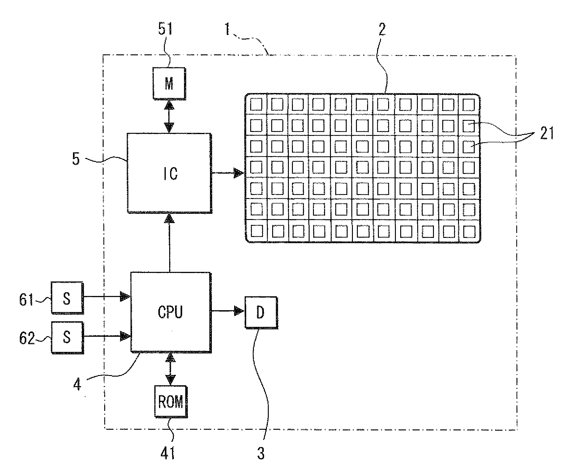
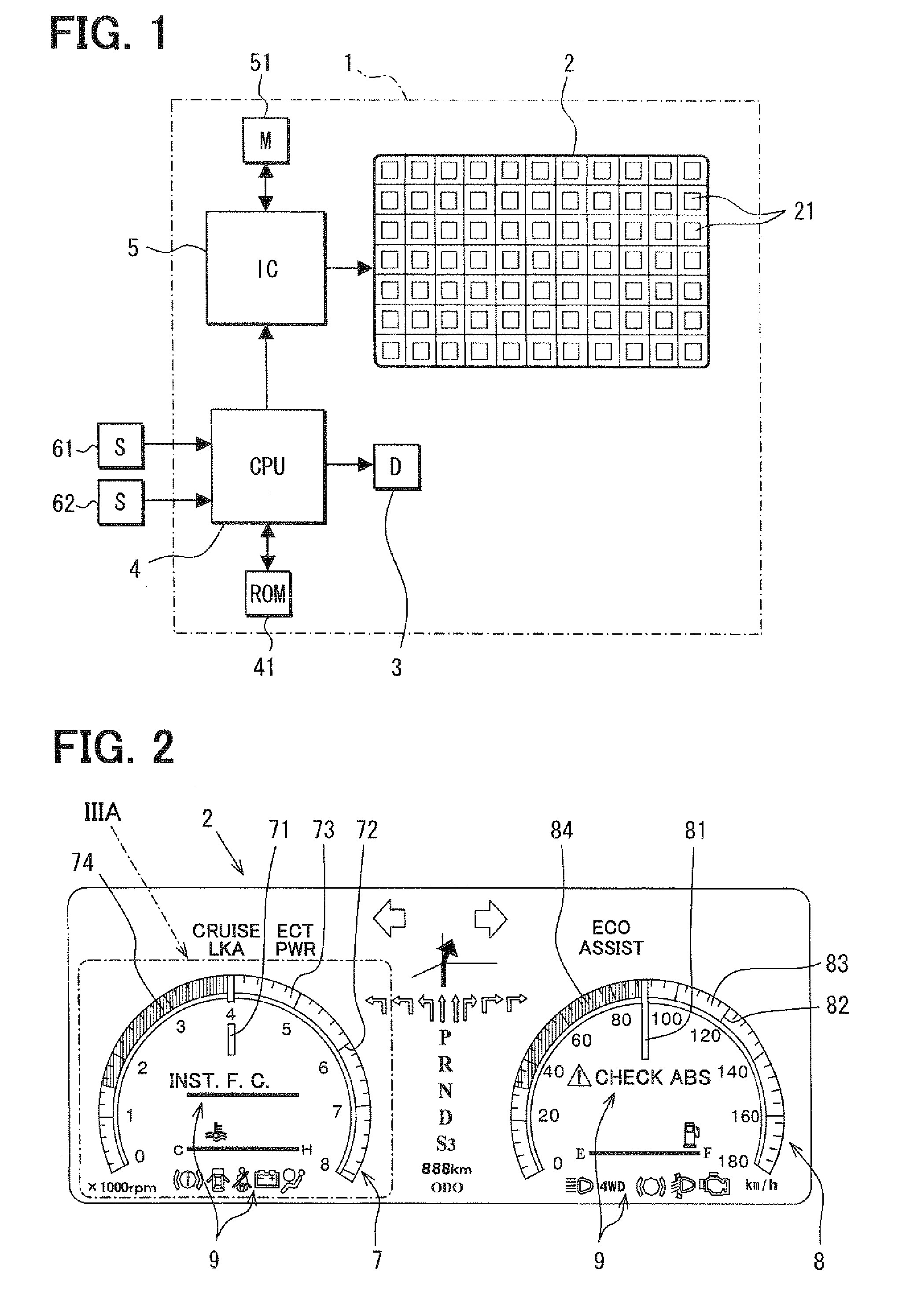
[0017]Referring to FIG. 1, a display device 1 is used as, for example, a vehicular display device. The display device 1 is provided with a display panel 2, a light emitting diode 3, a controller such as a CPU (central processing unit) 4, a lithography IC (integral circuit) 5 and a ROM (read only memory) 41, and an image memory 51 for rewriting memory data.

[0018]The display panel 2 is, for example, a liquid crystal panel 2, and is formed with a plurality of pixels 21 in a matrix shape. The liquid crystal panel 2 is, for example, a liquid crystal panel of an active matrix system driven by a thin film transistor (TFT) (not shown). Each of the pixels 21 houses a red pixel, a green pixel and a blue pixel therein, and a voltage is applied to a gate of TFT to control a voltage applied to each of the red pixel, the green pixel and the blue pixel in the pixel 21, th...


PUM


Abstract

A display device includes a display panel having a plurality of pixels in a form of matrix and a controller configured to control the plurality of pixels of the display panel so that an instrument image indicating an instrument is displayed on the display panel. The instrument image includes a scale image indicating a scale, and a pointer image indicating a pointer that is movable in accordance with an increase and decrease in a measured magnitude for indicating the measured magnitude in association with the scale image. The instrument image further includes a highlight image that is displayed in a predetermined pattern in accordance with at least one of a position and a motion of the pointer image.

Description

CROSS REFERENCE TO RELATED APPLICATION[0001]This application is based on Japanese Patent Application No. 2007-82710 filed on Mar. 27, 2007, the disclosure of which is incorporated herein by reference.FIELD OF THE INVENTION[0002]The present invention relates to a display device for displaying an instrument image indicating an instrument having a pointer.BACKGROUND OF THE INVENTION[0003]JP2006-21573A discloses a display device for a vehicle, which includes a display panel such as a liquid crystal panel in which a plurality of pixels is formed in the form of matrix The display panel displays instrument images indicating instruments each having a pointer. In addition, the display panel displays a navigation image for indicating information, such as a peripheral road map and a current position of the vehicle on the road map, in a middle portion of the display panel and between the instrument images.[0004]In a display device for displaying an instrument image such as an engine rotation sp...

Claims


Application Information

Patent Timeline
IPC IPC(8): G09G3/20
CPCB60K37/02B60K2350/1072G12B11/04G09G5/026G09G5/14G09G2340/12G09G2340/125G09G2380/10B60K35/60B60K35/213
Inventor KATOH, MIKIKUNO, MASAHIROMATSUNO, NAGAKO
Owner DENSO CORP
Learn More