Joined optical member, image display apparatus, and head-mounted display

a technology of jointing and optical members, applied in the direction of instruments, polarising elements, applications, etc., can solve the problems of unsatisfactory effect of preventing scratches on the exterior surfaces of individual optical members, more unhardened adhesive than, optical performance, etc., to prevent degradation of optical performance, prevent scratches, and strengthen the effect of preventing scratches

Inactive Publication Date: 2008-10-02
KONICA MINOLTA INC
View PDF10 Cites 50 Cited by
  • Summary
  • Abstract
  • Description
  • Claims
  • Application Information

AI Technical Summary

Benefits of technology

[0012]Thus, according to the invention, a surface coating layer is formed on the surfaces of part optical members that will remain as exterior surfaces after the part optical members are joined together, and the superfluous part of adhesive that has oozed outside of the surface coating layer is wiped off after it has hardened until it loses fluidity (that is, in a fully or half-hardened state). This helps prevent a recess from being formed in the adhesive between the joined surfaces, and thus helps prevent removal of more adhesive than is superfluous. Thus, it is possible to prevent degradation of the optical performance with which an outside world image can be viewed through the joint seam.
[0013]Moreover, either the relationship in adhesion strength among different pairs of materials is such that (the adhesion strength between the surface coating layer and the part optical members)>(the adhesion strength between the surface coating layer and the adhesive) and simultaneously (the adhesion strength between the part optical members and the adhesive)>(the adhesion strength between the surface coating layer and the adhesive), or the surface hardness of the surface coating layer is higher than the surface hardness of the part optical members. Thus, not only during removal of superfluous adhesive, but also in actual use, it is possible to prevent scratches on the exterior surfaces of the individual optical members, and thereby to obtain a stronger effect of preventing scratches than conventionally achieved. It is possible, in particular, to prevent degradation of optical performance on optical surfaces in actual use.

Problems solved by technology

Wiping off adhesive in its unhardened state, however, results in more unhardened adhesive than needs to be wiped off being removed, leaving a recess along the joint seam (the border between the individual optical members joined together).
This may degrade, for example, the optical performance with which an outside world image can be viewed through the joint seam.
Inconveniently, however, with the method disclosed in JP-A-2006-195073 mentioned above, the coating layer is removed either after the superfluous adhesive is removed or at the same time that it is removed.
This results in an unsatisfactory effect of preventing scratches on the exterior surfaces of the individual optical members.
That is, when the superfluous adhesive is removed, the coating layer present between the exterior surfaces of the optical members and the adhesive offers a certain effect of preventing scratches on the exterior surfaces; in actual use of the joined optical member, however, since no coating layer is present on the exterior surfaces any longer, no effect of preventing scratches on the exterior surfaces is obtained.
This may lead to degraded optical performance when those exterior surfaces are used as optical surfaces.

Method used


Image

  • Joined optical member, image display apparatus, and head-mounted display
  • Joined optical member, image display apparatus, and head-mounted display
  • Joined optical member, image display apparatus, and head-mounted display

Examples


Embodiment Construction

[0029]Embodiments of the invention will be described below with reference to the accompanying drawings.

1. HMD

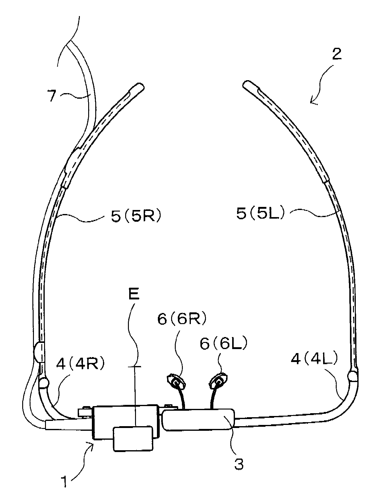
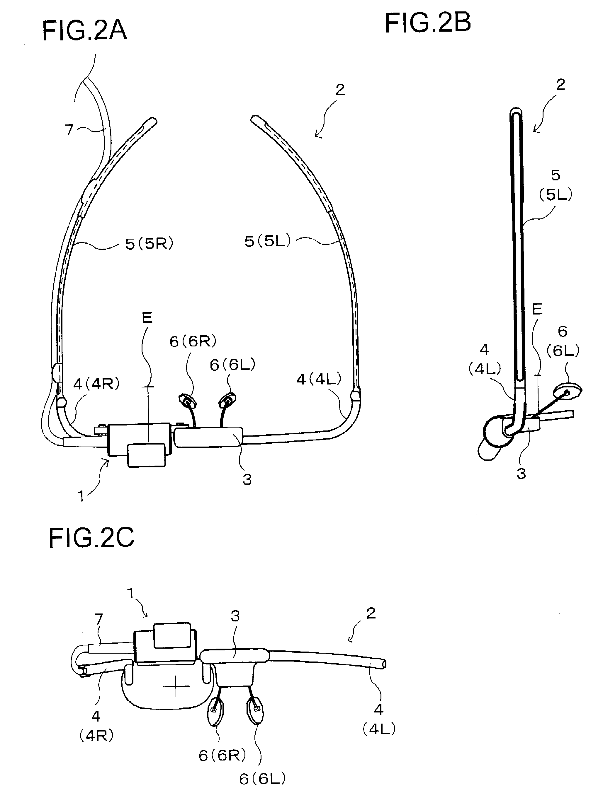
[0030]FIG. 2A is a plan view showing an outline of the structure of a HMD according to the invention, FIG. 2B is a side view of the HMD, and FIG. 2C is a front view of the HMD. The HMD has an image display apparatus 1 and a support mechanism 2 that supports it. As a whole, the HMD has an exterior appearance like that of common eye glasses with one lens (for example, the left-eye lens) removed.

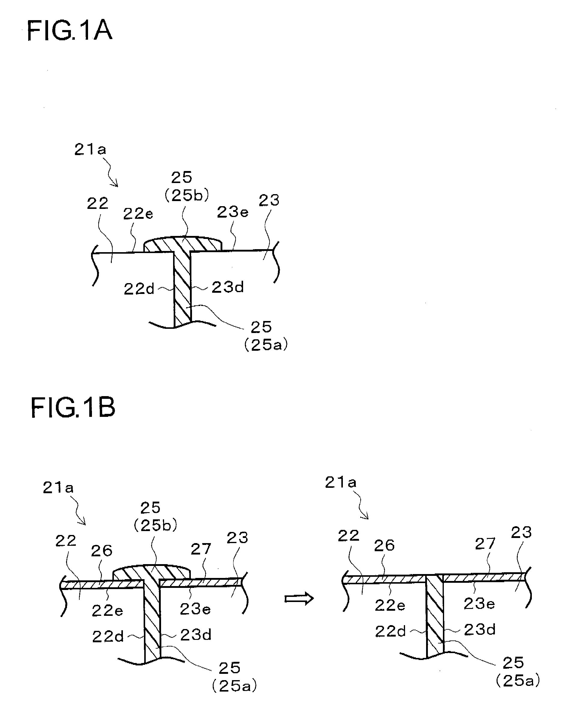
[0031]The image display apparatus 1 allows a viewer to view an outside world image in a see-through fashion, and simultaneously displays an image to present it as a virtual image to the viewer. In the image display apparatus 1 shown in FIG. 2C, the part thereof corresponding to the right-eye lens of eyeglasses is composed of an eyepiece prism 22 and a deflector prism 23 (for both, see FIG. 3), which will each be described later, joined together. The structure of the image display apparat...


PUM

PropertyMeasurementUnit
center wavelengthsaaaaaaaaaa

Abstract

In a joined optical member, let the adhesion strength between a surface coating layer and an eyepiece prism be A1, the adhesion strength between the surface coating layer and a deflector prism be A2, the adhesion strength between the surface coating layer and adhesive be A3, and the adhesion strength between, at one end, the adhesive and, at the other, the eyepiece prism and the deflector prism be A4, then A1 (A2)>S3 and simultaneously A4>A3. This makes removal of superfluous adhesive on the surface coating layer easy, and prevents scratches on the exterior surfaces. Even after removal of superfluous adhesive, the surface coating layer remains on the exterior surfaces of the eyepiece prism and the deflector prism. This prevents scratches on the exterior surfaces in actual use, and prevents degradation of optical performance.

Description

[0001]This application is based on Japanese Patent Application No. 2007-083902 filed on Mar. 28, 2007 and Japanese Patent Application No. 2008-007520 filed on Jan. 17, 2008, the contents of which are hereby incorporated by reference.BACKGROUND OF THE INVENTION[0002]1. Field of the Invention[0003]The present invention relates to a joined (or bonded, or cemented) optical member having a plurality of optical members (part optical members) joined together with adhesive, also relates to an image display apparatus incorporating such a joined optical member, and further relates to a head-mounted display (hereinafter also “HMD”) incorporating such an image display apparatus.[0004]2. Description of Related Art[0005]When two optical members are joined together with adhesive to form a joined optical member, the superfluous adhesive that oozes out from between the joined surfaces needs to be removed. This is achieved by, for example, the method disclosed in JP-A-H6-308349. According to this met...

Claims


Application Information

Patent Timeline
Patent Type & Authority Applications(United States)
IPC IPC(8): G03H1/00
CPCG02B27/017G02B27/0172G02B2027/0174Y10S359/90
Inventor NODA, TETSUYA
Owner KONICA MINOLTA INC
Why Eureka
Try Eureka