Method and apparatus for writing network packets into computer memory

a network packet and computer memory technology, applied in the field of computer networks, can solve the problems of consuming some of the available processing cycles of the computer processor unit, reducing the impact of copy operation, and undesirable copy operation

Inactive Publication Date: 2008-10-02
GADELRAB SERAG
View PDF10 Cites 61 Cited by
  • Summary
  • Abstract
  • Description
  • Claims
  • Application Information

AI Technical Summary

Problems solved by technology

This copy operation is undesirable because it consumes bandwidth resources from the Computer Memory 20, the Computer Interconnect 30 which moves the data between the Computer Memory 20, and the Computer Processor Unit 45.
Another undesirable trait of the copy operation is that it also consume

Method used


Image

  • Method and apparatus for writing network packets into computer memory
  • Method and apparatus for writing network packets into computer memory
  • Method and apparatus for writing network packets into computer memory

Examples


Embodiment Construction

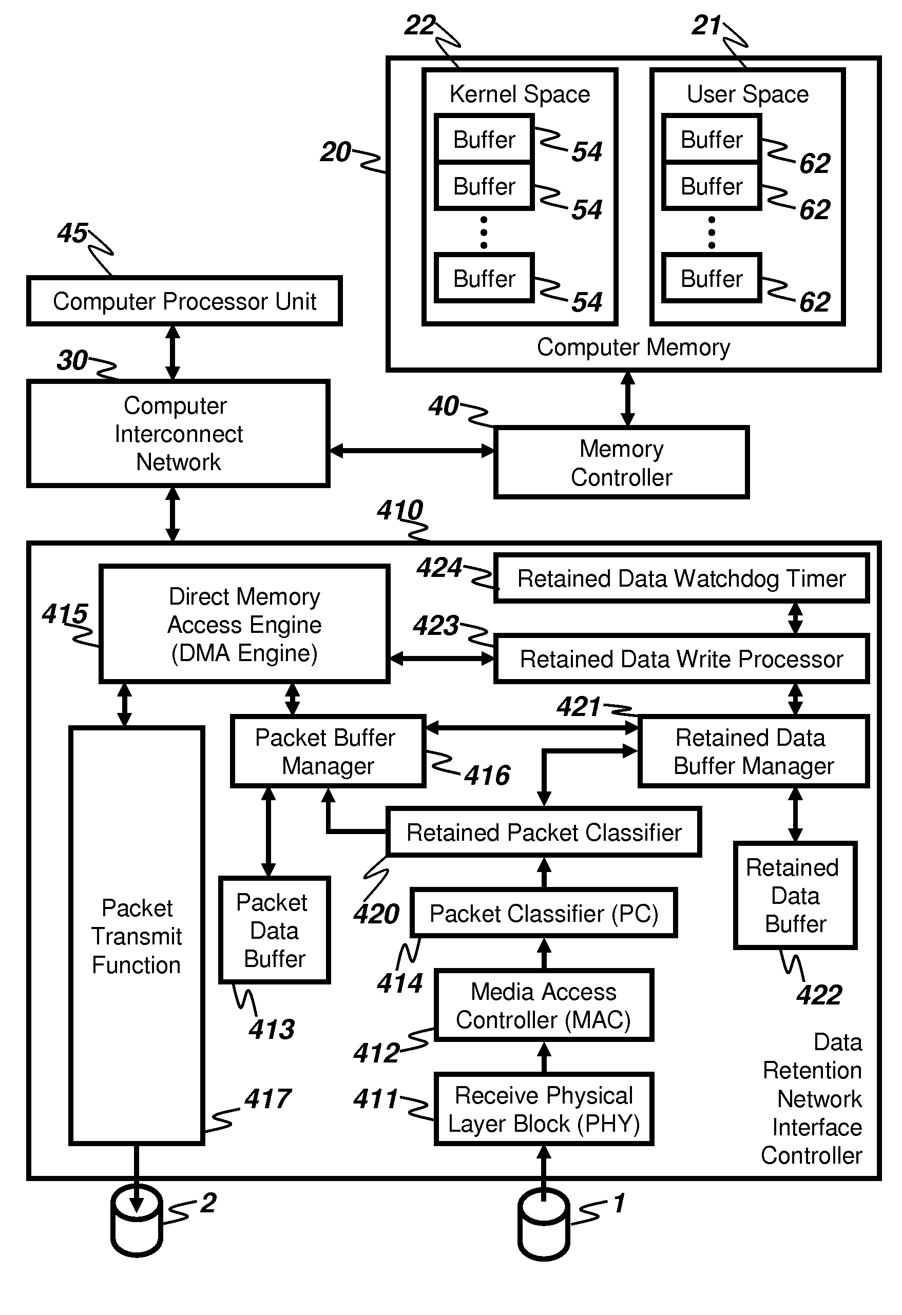
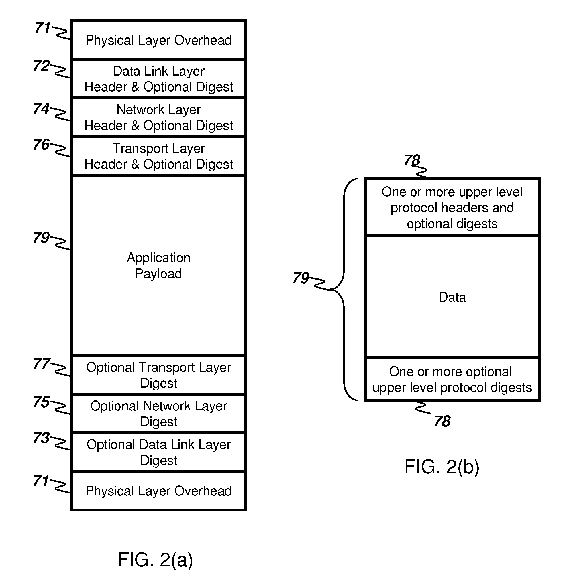
[0035]The present invention is a method and apparatus that reduces the usage of Computer Memory 20 bandwidth associated with writing data contained in the Application Payload 79 of arriving packets into the corresponding User Space Buffer(s) 62.

[0036]In general, the architectural premise of the present invention is that all information required by packet processing software layers within the KSSL 50, to process the arriving packets, to determine the amount of Application Payload 79 to be written into User Space Buffers 62, and to locate the User Space Buffers that the Application Payload 79 data is to be written into, can be obtained from the different protocol headers of each packet and from the validation operations associated with each of the packet protocols. The present invention reduces the amount of used Computer Memory 20 bandwidth for some or all arriving packets by performing protocol validation and writing the protocol headers of the said packets to the Kernel Packet Buff...


PUM


Abstract

An apparatus receives packets from a network and inserts the packet data into the memory of a computer system. The invention reduces the amount of computer system memory bandwidth required to receive packets through the use of a retained data buffer. Packet headers and a summary of packet validation results are processed by network stacks within the computer system to identify the intended memory buffer in which the packet payload is to be placed. Packet payload data is directly placed from the retained data buffer to the intended memory buffer without the use of intermediate buffers. A preferred embodiment includes a data retention network interface card (DRNIC) which includes the required data retention buffer for use in direct placement of received data.

Description

FIELD OF INVENTION[0001]The present invention relates to computer networks, and more particularly, to the methods and apparatus by which network packets that arrive at a computer are written into the computer's memory. The present invention is particularly concerned with reducing the number of computer memory read and write operations required to insert arriving network packets into the computer memory.BACKGROUND ART[0002]FIG. 1 is a block diagram representation of an exemplary computer system that receives and transmits packets using a network connection. FIG. 1 shows the path taken by incoming network packets that arrive from the physical receive network links 1 and travel from the Network Interface Controller (NIC) 10 to their ultimate destination in the Computer Memory 20. FIG. 1 also shows the path taken by outgoing network packets that travel from the Computer Memory 20 to the physical transmit network link 2 through the Network Interface Controller (NIC) 10. The Network Inter...

Claims


Application Information

Patent Timeline
IPC IPC(8): H04L12/56
CPCH04L49/90H04L49/9063
Inventor GADELRAB, SERAG
Owner GADELRAB SERAG
Why Eureka
Try Eureka