
Regions of interest for quality adjustments

a quality adjustment and region technology, applied in the field of regions of interest for quality adjustments, can solve the problems of lossless compression, lossy compression, and reduced bit rate due to video complexity, so as to reduce the bit rate of information, remove redundancy, and reduce the effect of fidelity

Inactive Publication Date: 2008-10-02
MICROSOFT TECH LICENSING LLC
View PDF99 Cites 77 Cited by
  • Summary
  • Abstract
  • Description
  • Claims
  • Application Information

AI Technical Summary

Benefits of technology

[0049]The present application describes techniques and tools for adjusting quality settings (e.g., quantization parameters) for regions of interest. For example, the perceptual quality of video is improved by allowing a user to identify regions of interest that specify quantization adjustments for corresponding parts of video pictures.
[0051]In one aspect, a region of interest is identified for a video picture. Typically, the video picture is comprised of units such as macroblocks, and the region of interest corresponds to a subset of macroblocks in the picture. Initial region-of-interest encoding settings established by a video encoder (e.g., quantization step sizes for macroblocks corresponding to the region of interest) are adjusted relative to encoder settings for other parts of the video picture, by changing the region-of-interest settings and / or the encoder settings for other parts of the picture. The adjustment is based at least in part on region-of-interest information associated with the region of interest. The region-of-interest information includes, for example, dead zone information and quantization step size information. Quantization step sizes and / or dead zone sizes can be reduced (to improve visual quality) or increased (to reduce bit rate). The region of interest can be identified and quality adjustment information can be provided based on input received from a user interface (e.g., graphical user interface, command line interface, eye tracking device, etc.).

Problems solved by technology

Compression can be lossless, in which quality of the video does not suffer but decreases in bit rate are limited by the complexity of the video.
Or, compression can be lossy, in which quality of the video suffers but decreases in bit rate are more dramatic.
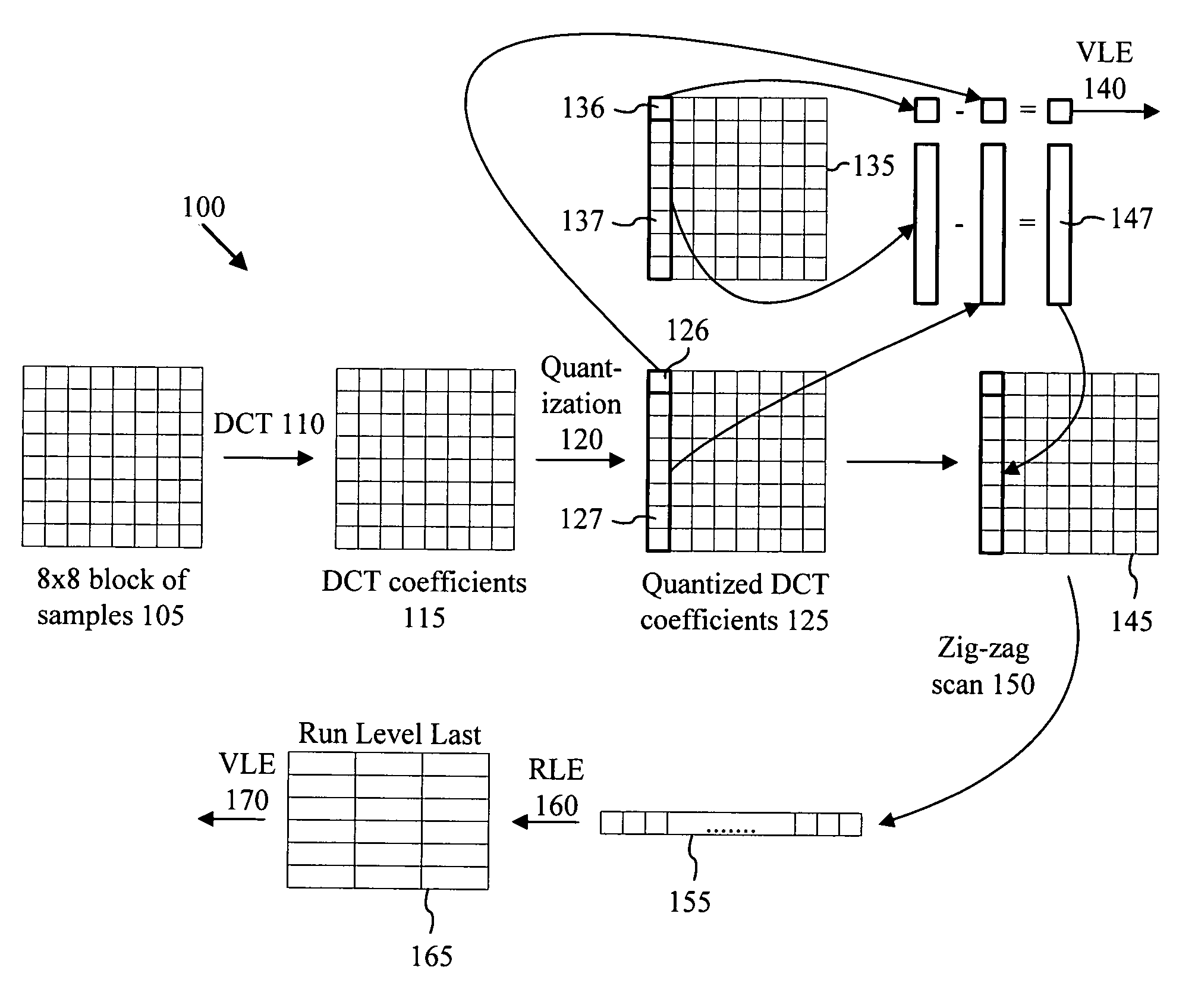
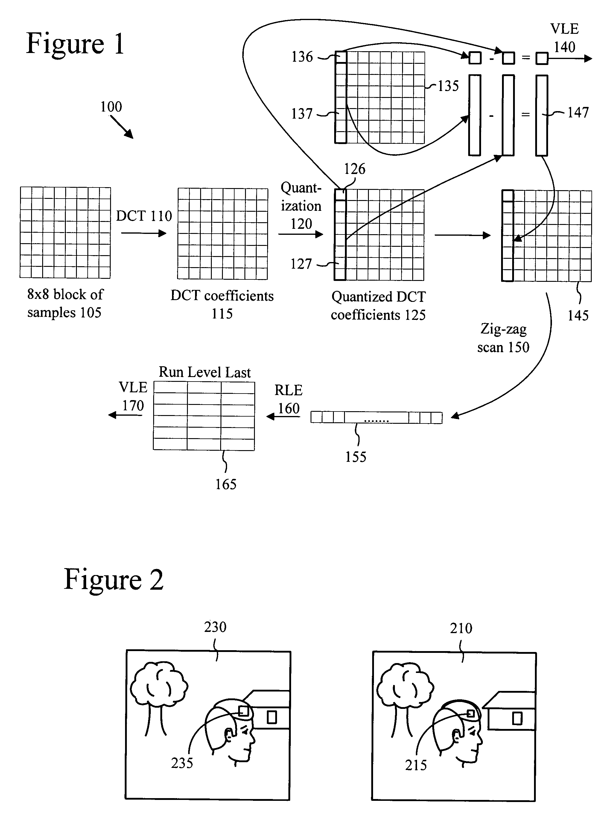
The DCT operation itself is lossless or nearly lossless.
Since low frequency DCT coefficients tend to have higher values, quantization typically results in loss of precision but not complete loss of the information for the coefficients.
In addition, in some cases high frequency DCT coefficients are quantized more coarsely than low frequency DCT coefficients, resulting in greater loss of precision / information for the high frequency DCT coefficients.
Lossless compression techniques reduce bit rate at no cost to quality, but can only reduce bit rate up to a certain point.
In contrast, with lossy compression, the quality suffers somewhat but the achievable decrease in bit rate is more dramatic.
Lossy compression techniques can be used to reduce bit rate more than lossless compression techniques, but some of the reduction in bit rate is achieved by reducing quality, and the lost quality cannot be completely recovered.
As mentioned above, lossy compression tends to cause a decrease in quality.
In some cases, quantization produces visible artifacts that tend to be more artificial-looking and visually distracting than simple loss of fine detail.
For example, smooth, un-textured content is susceptible to contouring artifacts—artifacts that appear between regions of two different quantization output values—because the human visual system is sensitive to subtle variations (particularly luma differences) in smooth content.

Method used


Image

  • Regions of interest for quality adjustments
  • Regions of interest for quality adjustments
  • Regions of interest for quality adjustments

Examples


Embodiment Construction

[0073]The present application relates to techniques and tools for quality adjustments (e.g., quantization adjustments in video pictures) using regions of interest. In various described embodiments, a video encoder incorporates techniques for encoding video, and corresponding signaling techniques for use with a bitstream format or syntax comprising different layers or levels. Some of the described techniques and tools can be applied to interlaced or progressive frames.

[0074]Various alternatives to the implementations described herein are possible. For example, techniques described with reference to flowchart diagrams can be altered by changing the ordering of stages shown in the flowcharts, by repeating or omitting certain stages, etc. As another example, although some implementations are described with reference to specific macroblock formats, other formats also can be used.

[0075]The various techniques and tools can be used in combination or independently. Different embodiments impl...


PUM


Abstract

Quality settings established by an encoder are adjusted based on information associated with regions of interest (“ROIs”). For example, quantization step sizes can be reduced (to improve quality) or increased (to reduce bit rate). ROIs can be identified and quality settings can be adjusted based on input received from a user interface. An overlap setting can be determined for a portion of a picture that corresponds to an ROI overlap area. For example, an overlap setting is chosen from step sizes corresponding to a first overlapping ROI and a second overlapping ROI, or from relative reductions in step size corresponding to the first ROI and the second ROI. ROIs can be parameterized by information (e.g., using data structures) that indicates spatial dimensions of the ROIs and quality adjustment information (e.g., dead zone information, step size information, and quantization mode information).

Description

BACKGROUND[0001]With the increased popularity of DVDs, music delivery over the Internet, and digital cameras, digital media have become commonplace. Engineers use a variety of techniques to process digital audio, video, and images efficiently while still maintaining quality. To understand these techniques, it helps to understand how the audio, video, and image information is represented and processed in a computer.I. Representation of Media Information in a Computer[0002]A computer processes media information as a series of numbers representing that information. For example, a single number may represent the intensity of brightness or the intensity of a color component such as red, green or blue for each elementary small region of a picture, so that the digital representation of the picture consists of one or more arrays of such numbers. Each such number may be referred to as a sample. For a color image, it is conventional to use more than one sample to represent the color of each e...

Claims


Application Information

Patent Timeline
IPC IPC(8): H04N11/04
CPCH04N19/147H04N19/61H04N19/17H04N19/162H04N19/124
Inventor LIN, CHIH-LUNGLEE, MING-CHIEHSPEARS, STACEYGARRETT, PHILIP LAWRENCEMURCHING, ANIL MADHAVBEAUFORD, AMY JENNIFERHOLCOMB, THOMAS W.ZUO, XIPING
Owner MICROSOFT TECH LICENSING LLC
Learn More