X-ray tomosynthesis device

a tomosynthesis device and x-ray technology, applied in the direction of x-ray tube electrodes, cathode ray concentrating/focusing/directing, diagnostics, etc., can solve the problems of significant mechanical complexity, increased disadvantage, complicated and expensive manufacture of known devices, etc., and achieve high image quality of x-ray images. , the effect of manufacturing more economically

Inactive Publication Date: 2008-10-02
YXLON INT FEINFOCUS
View PDF14 Cites 36 Cited by
  • Summary
  • Abstract
  • Description
  • Claims
  • Application Information

AI Technical Summary

Benefits of technology

[0012]An object of the present invention is to provide an X-ray tomosynthesis device which is simplified and which can therefore be manufactured more economically, and at the same time allows a high image quality of the X-ray images.

Problems solved by technology

A disadvantage of these known devices is that, due to the required motion of the X-ray tube as well as the X-ray detector relative to the object to be examined, significant masses must be moved, which entails significant mechanical complexity and therefore makes the manufacture of the known devices complicated and expensive.
This disadvantage is heightened due to the fact that the motion of the masses must be carried out with great precision in order to achieve sufficient image quality, and must also be synchronized with the motion of the X-ray source on the one hand and the motion of the detector on the other hand.
However, such a device still requires motion of the X-ray tube, so that in principle the above-described disadvantages remain.
These known devices as well have the primary disadvantage that significant masses must be moved.
For these devices as well, it is disadvantageous that significant masses must be moved with great precision.
The necessary mirror system also entails significant mechanical complexity and makes the manufacture of the known devices costly.

Method used


Image

  • X-ray tomosynthesis device
  • X-ray tomosynthesis device
  • X-ray tomosynthesis device

Examples


Embodiment Construction

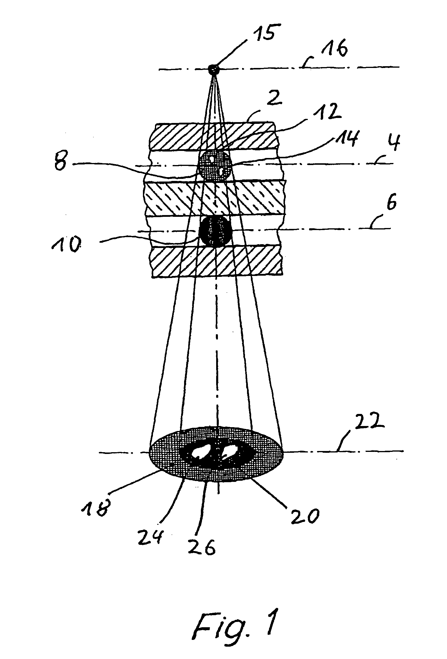
[0075]FIG. 1 shows a multilayer printed circuit board 2 during an examination using X-ray radiation in an imaging method. The multilayer printed circuit board 2 has soldering connections, situated in different planes 4, 6, in the form of solder balls, of which two solder balls 8, 10 are shown by way of example in FIG. 1, solder ball 8 having defects in the form of bubbles 12, 14.

[0076]The multilayer printed circuit board 2 is examined by irradiation with X-ray radiation which is generated by an X-ray radiation source, the focal spot 15 of which lies in a focal spot plane 16. Irradiation of the solder balls 8, 10 produces irradiation images 18, 20 which are recorded in a detector plane 22 by a detector. This results in irradiation images 24, 26 of the bubbles 10, 12.

[0077]As shown in FIG. 1, the irradiation images 18, 20 of the solder balls 8, 10 are superimposed in the detector plane 22. Thus, the irradiation images 24, 26 of the bubbles 10, 12 are discernible on the image recorded ...


PUM


Abstract

X-ray tomosynthesis device includes a target and a device configured for directing a particle beam of electrically charged particles onto the target which emits X-ray radiation for irradiating a sample to be examined when the electrically charged particles strike the target, in use. The target includes at least one support element on which a plurality of mutually spaced target elements are provided, and each mutually spaced target element only partially covers the at least one support element. A deflection device is provided, and the deflection device is configured for causing the particle beam to be deflected in order to strike the plurality of mutually spaced target elements, in use.

Description

CROSS-REFERENCE TO RELATED APPLICATIONS[0001]This application is a continuation of application no. PCT / EP2006 / 010441, filed Oct. 31, 2006, which claims the priority of German application no. 20 2005 017 496.3, filed Nov. 7, 2005, and each of which is incorporated herein by reference.FIELD OF THE INVENTION[0002]The invention relates to an X-ray tomosynthesis device of the type configured for directing a particle beam of electrically charged particles onto a target which emits X-ray radiation for irradiating a sample to be examined when the electrically charged particles strike the target, in use.BACKGROUND OF THE INVENTION[0003]Such devices are generally known, and are used, for example, for examining electronic components, printed circuit modules, or printed circuit boards.[0004]X-ray laminography or tomosynthesis methods are based on the principle of relative motion of an X-ray beam from an X-ray source with respect to an object to be examined. Technical details concerning X-ray la...

Claims


Application Information

Patent Timeline
Patent Type & Authority Applications(United States)
IPC IPC(8): A61B6/00
CPCG01N23/046H01J35/12H01J35/14H01J35/18G01N2223/419H01J2235/086H01J2235/1204H01J2235/1291H01J2235/186H01J35/30G01N23/044H01J35/186H01J35/153G01N23/223
Inventor REINHOLD, ALFRED
Owner YXLON INT FEINFOCUS
Why Eureka
Try Eureka