This helps you quickly interpret patents by identifying the three key elements:
Problems solved by technology
Method used
Benefits of technology
Benefits of technology
[0022]It is an object of the present invention to provide an active noise control apparatus, which is capable of generating a control signal according to a simple digital signalprocessing method, benefits from a reduced computational burden in generating the control signal, and is relatively inexpensive to manufacture.
[0023]Another object of the present invention is to provide an active noise control apparatus, which is capable of stably silencing road noise in order to reliably reduce the road noise.
Problems solved by technology
While the vehicle is running, vibrations of the tires caused by the road are transmitted through suspensions to the vehicle body, thereby producing an aperiodic drumming noise (road noise) in the passenger compartment.
As a result, the aperiodic-noise-compatible ANC is relatively expensive to manufacture.
Furthermore, since the aperiodic-noise-compatible ANC generates a control signal at the resonant frequencies, while updating the filter coefficient of the adaptive filter from time to time, the control unit suffers from an increased computational burden in connection with generating the control signal.
As a result, the control unit requires a large circuit scale, thereby causing the ANC including the control unit to have a large unit size.
However, it is difficult for an ANC having such a large unit size to find sufficient installation space inside the vehicle.
In addition, it is also difficult to combine the ANC having such a large unit size with a digital audio unit.
Method used
Image
Click on the blue label to locate the original text in one second.
Reading with bidirectional positioning of images and text.
Examples
first embodiment
[0136]FIGS. 8 and 9 show in block form an ANC 10A according to the present invention, which is a specific example of the first fundamental concept (see FIGS. 1 through 5).
[0137]The ANC 10A is incorporated in a vehicle 12 as shown in FIG. 8. The ANC 10A basically comprises an ANC electronic controller 20 including a microcomputer 52 (see FIG. 9), a speaker 22 disposed in a given position in the vehicle 12, e.g., below a front seat 24, and a microphone 18 disposed near the position of an ear of a passenger, not shown, in a passenger compartment 14 of the vehicle 12, e.g., near the headrest 26 of the front seat 24.
[0138]The noise at the position of the microphone 18 includes (1) a noise generated in the passenger compartment 14 by vibrations of an engine (not shown) or the like in the vehicle 12, and a noise generated by a noise source, and a periodic noise {engine muffled sound (engine noise)} generated in the passenger compartment 14 by the above vibrations, and by vibrations of the ...
second embodiment
[0150]An ANC 10B which is a specific example of the second fundamental concept (see FIGS. 6 and 7), will be described below with reference to FIG. 10.
[0151]The ANC 10B includes the filter 70 described above with reference to FIGS. 6 and 7. Therefore, the ANC 10B has one filter fewer than the filters used in the ANC 10A. As a result, the computational burden on the ANC 10B in generating the control signal y(n) is further reduced.
third embodiment
[0152]An ANC 10C will be described below with reference to FIGS. 11 and 12.
[0153]The ANC 10C differs from the ANC 10A (see FIG. 9) according to the first embodiment, in that a bandpass filter (BPF) 72 is connected to the input side of the microcomputer 52.
[0154]From the canceling error signal e(n) output from the LPF 66, the BPF 72 passes and outputs, to the microcomputer 52, only a signal within a predetermined frequency band, having a central frequency equal to the control frequency of 40 [Hz], for example, of the control signal y(n). In other words, from the canceling error signal e(n), the BPF 72 passes only a signal corresponding to a road noise (resonant sound) having a central frequency of about 40 [Hz], and outputs the signal through the ADC 59 to the microcomputer 52.
[0155]FIG. 12 shows sound pressure vs. frequency characteristics of a noise at the position of the microphone 18 (see FIG. 12). FIG. 12 illustrates a comparison between a characteristic curve plotted when a si...
PUM
Abstract
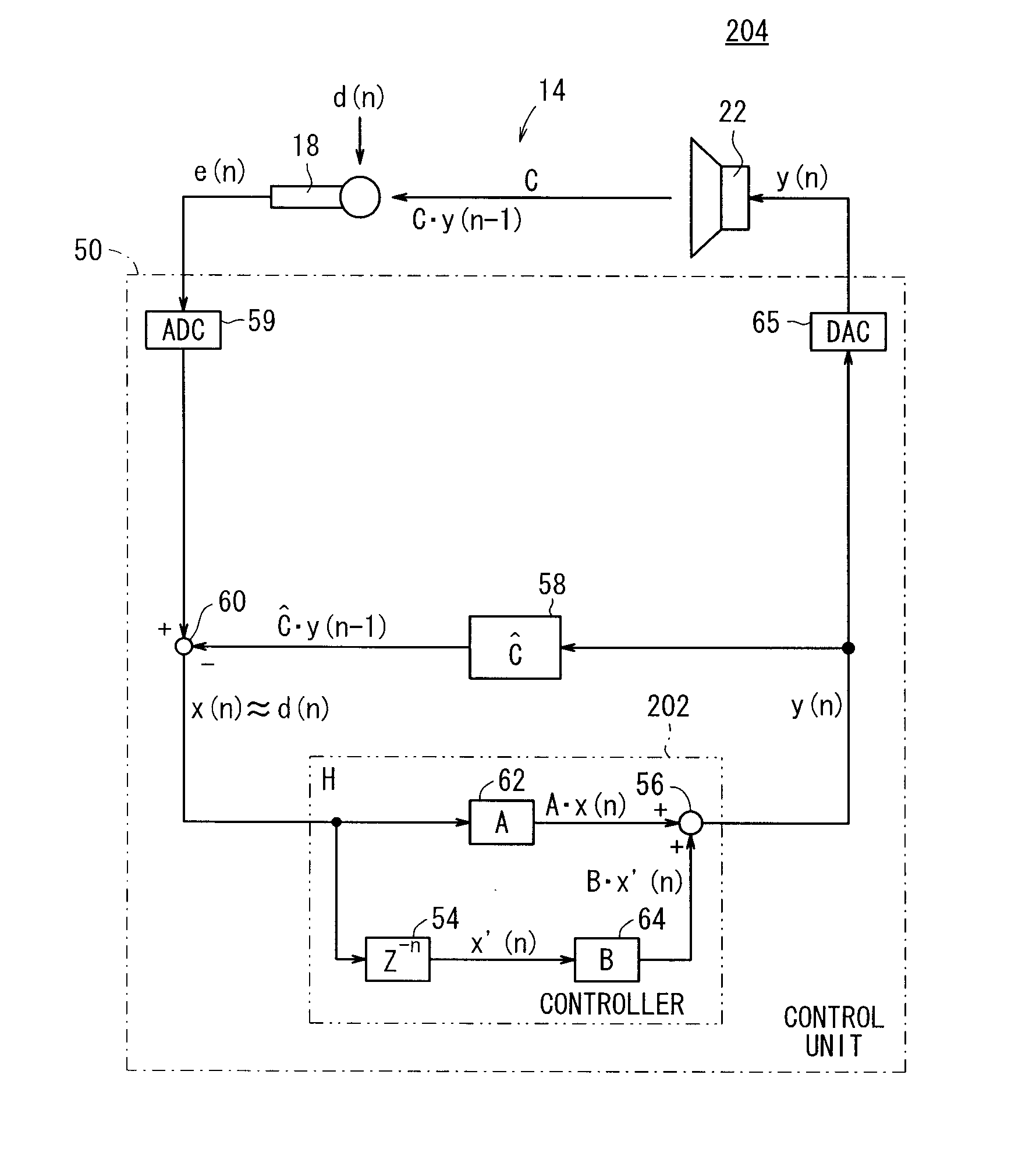
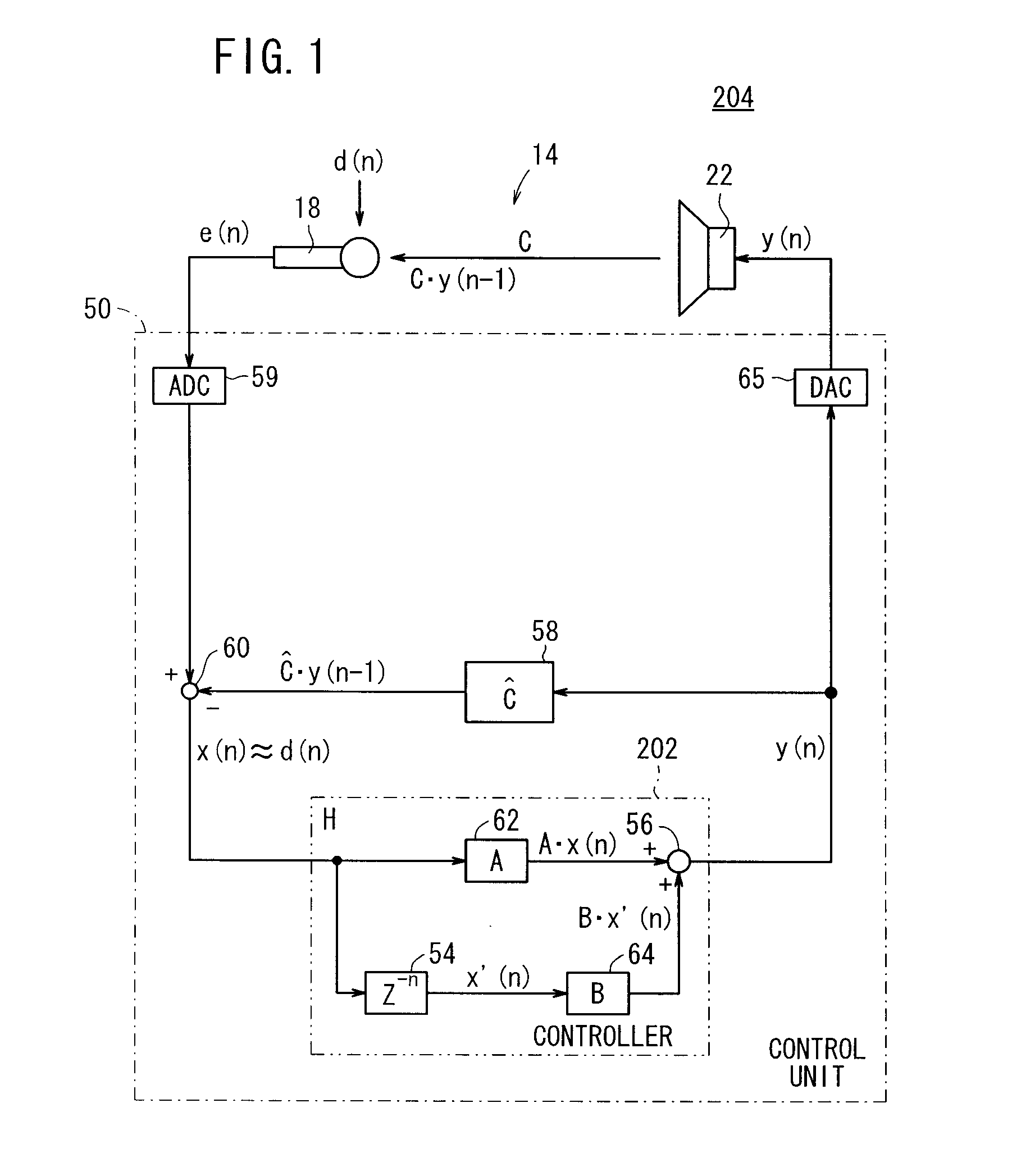
A subtractor subtracts an echo canceling signal (Ĉ·y1(n−1)) from a canceling error signal (e(n)) to estimate the resonant noise (d(n)) to be silenced at a position of a microphone, and outputs a first basic signal (x1(n)) representing the estimated resonant noise d(n) as an input signal supplied to a controller. In the controller, a delay filter generates a second basic signal (x′(n)) by delaying the first basic signal (x1(n)) by a time value (Z−n) The controller generates a control signal (x(n)) based on the first basic signal (x(n)) and the second basic signal (x′(n)).
Description
BACKGROUND OF THE INVENTION[0001]1. Field of the Invention[0002]The present invention relates to an active noise control apparatus for reducing an in-compartment noise with a cancellation sound, which is opposite in phase to the in-compartment noise, and more particularly to an active noise control apparatus for reducing a drumming noise (hereinafter also referred to as “road noise”), which is generated in the passenger compartment of a vehicle while the vehicle is running.[0003]2. Description of the Related Art[0004]Heretofore, there has been known in the art an active noise control apparatus (hereinafter also referred to as a “periodic-noise-compatible ANC”) for reducing noise (hereinafter referred to as “engine muffled sound” or “engine noise”) caused by a vibratory noise, which is produced by a vibratory noise source such as an engine or the like on a vehicle and generated periodically in synchronism with the rotation of the engine, by generating a control signal via a control u...
Claims
Application Information
Patent Timeline
Application Date:The date an application was filed.
Publication Date:The date a patent or application was officially published.
First Publication Date:The earliest publication date of a patent with the same application number.
Issue Date:Publication date of the patent grant document.
PCT Entry Date:The Entry date of PCT National Phase.
Estimated Expiry Date:The statutory expiry date of a patent right according to the Patent Law, and it is the longest term of protection that the patent right can achieve without the termination of the patent right due to other reasons(Term extension factor has been taken into account ).
Invalid Date:Actual expiry date is based on effective date or publication date of legal transaction data of invalid patent.

