Electrophotographic image forming apparatus, developing apparatus, and coupling member

a technology of developing apparatus and developing roller, which is applied in the direction of electrographic process apparatus, yielding coupling, instruments, etc., can solve the problems of difficult to prevent non-uniform achieve improvement of image forming speed, and smooth rotation of developing roller

Active Publication Date: 2008-10-02
CANON KK
View PDF49 Cites 172 Cited by
  • Summary
  • Abstract
  • Description
  • Claims
  • Application Information

AI Technical Summary

Benefits of technology

[0023]Further, according to the present invention, it is possible to provide a developing apparatus capable of mounting with and demounting from a driving shaft provided to the apparatus main assembly from a direction substantially perpendicular to an axial direction of the driving shaft by movement of a moving member in one direction. According to the present invention, it is also possible to provide the electrophotographic image forming apparatus using the developing apparatus and a coupling member used in the developing apparatus.
[0024]Further, according to the present invention, it is possible to provide a developing apparatus capable of mounting with and demounting from a driving shaft provided to the apparatus main assembly from a direction substantially perpendicular to an axial direction of the driving shaft by movement of a moving member in one direction and capable of smoothly rotating a developing roller. According to the present invention, it is also possible to provide the electrophotographic image forming apparatus using the developing apparatus and a coupling member used in the developing apparatus.
[0025]Further, according to the present invention, it is possible to provide a developing apparatus including a coupling member capable of taking a rotating force transmitting angular position for transmitting a rotating force from the apparatus main assembly to a developing roller, a pre-engagement angular position at which the coupling member is inclined from the rotating force transmitting angular position and is in a state before

Problems solved by technology

For this reason, it is difficult to prevent ro

Method used


Image

  • Electrophotographic image forming apparatus, developing apparatus, and coupling member
  • Electrophotographic image forming apparatus, developing apparatus, and coupling member
  • Electrophotographic image forming apparatus, developing apparatus, and coupling member

Examples


embodiment 1

(1) Brief Description of Developing Cartridge

(Developing Device)

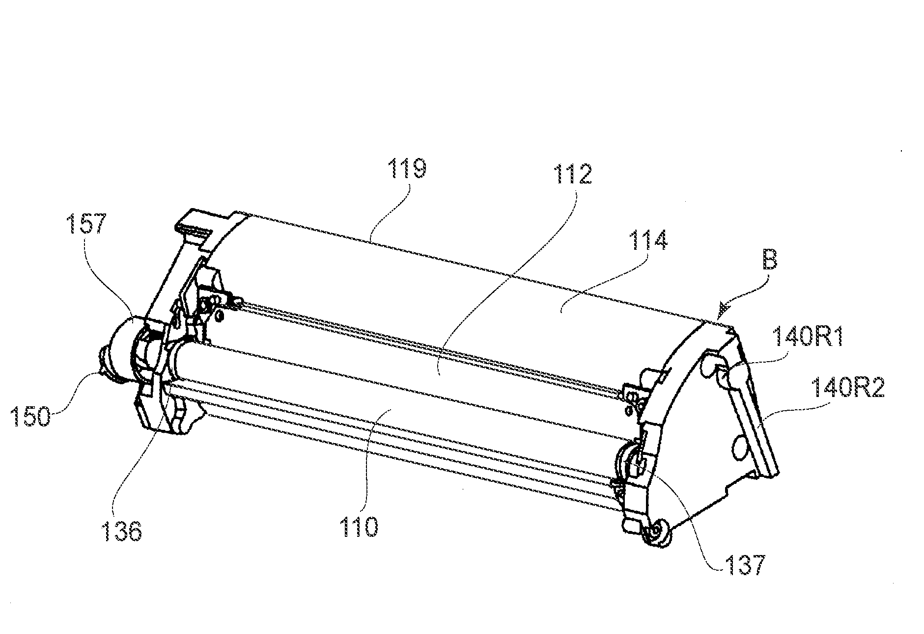
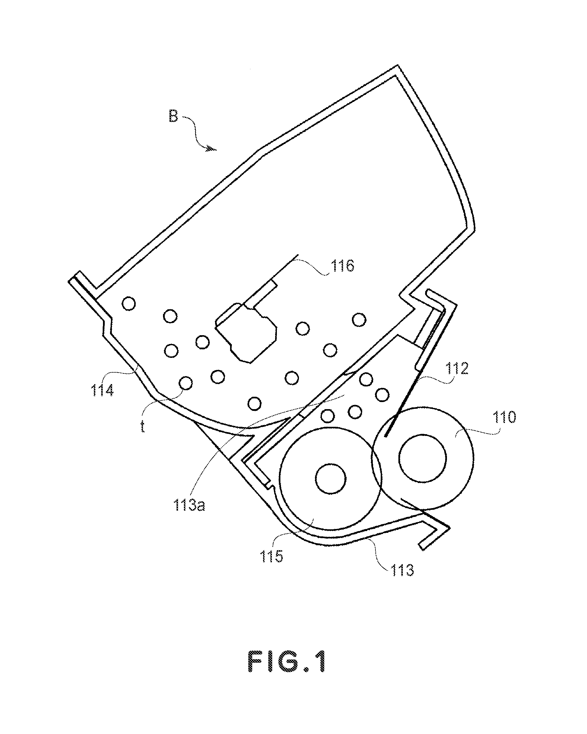
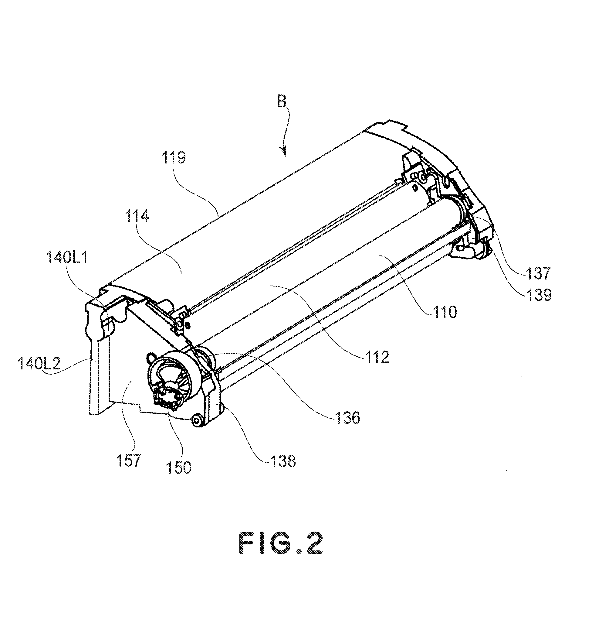
[0111]First, with reference to FIGS. 1 to 4, a developing cartridge B as a developing device to which an embodiment of the present invention is applied (hereinafter simply referred to as a “cartridge”) will be described. FIG. 1 is a sectional view of the cartridge B. FIGS. 2 and 3 are perspective views of the cartridge B. FIG. 4 is a sectional view of a color electrophotographic image forming apparatus main assembly A (hereinafter referred to as an “apparatus main assembly”).

[0112]This cartridge B can be mounted to and demounted from a rotary C provided to the apparatus main assembly A by a user.

[0113]Referring to FIGS. 1 to 3, the cartridge B includes a developing roller 110. The developing roller is rotated by receiving a rotating force from the apparatus main assembly A through a coupling mechanism described later during a developing function. In a developer accommodating frame 114, a developer t of a predetermined c...

embodiment 2

[0287]Referring to FIG. 36-FIG. 38, the second embodiment to which applied the present invention will be described.

[0288]In this embodiment, a means for inclining the axis of the coupling relative to the axis of the developing roller.

[0289]In the description of this embodiment, the same reference numerals as in Embodiment 1 are assigned to the elements having the corresponding functions in this embodiment, and the detailed description thereof is omitted for simplicity. This applies also about the other embodiment described in the below.

[0290]FIG. 36 is a perspective view which illustrates a coupling locking member (this is peculiar to the present embodiment) pasted on the supporting member. FIG. 37 is an enlarged perspective view of a major part of the driving side of the cartridge. FIG. 38 is a perspective view and a longitudinal sectional view which illustrate an engaged state between the drive shaft and the coupling.

[0291]As shown in FIG. 36, the supporting member 3157 has a spac...

embodiment 3

[0305]Referring to FIG. 39-FIG. 42, a third embodiment of the present invention will be described.

[0306]The description will be made as to means for inclining the axis L2 relative to the axis L1.

[0307]As shown in FIG. 39 (perspective view), a coupling pressing member peculiar to the present embodiment is mounted to the supporting member. FIG. 40 is a perspective view illustrating the coupling pressing member. FIG. 41 is an enlarged perspective view of the major part of the driving side of the cartridge. FIG. 42 is a perspective view illustrating the engaging operation and a longitudinal sectional view of the coupling.

[0308]As shown in FIG. 39, spring supporting portions 4157e1, 4157e2 are provided on the inner surface 4157i of the supporting member (mounting member) 4157. In addition, the coil parts 4159b, 4159c of torsion coil springs (coupling urging members) 4159 are mounted to the supporting portions 4157e1, 4157e2. And, as shown in FIG. 40, a contact portion 4159a of the urging...


PUM


Abstract

A developing device usable with an electrophotographic image forming apparatus includes a driving shaft having a rotating force applying portion, and a movable member. The developing device is mounted to the moving member and includes a developing roller, and a coupling member that includes a rotating force receiving portion and a rotating force applying portion. The coupling member is capable of taking (i) a rotational force transmitting angular position for transmitting the rotational force to the developing roller, (ii) a pre-engagement angular position taken before the coupling member is engaged with the rotating force applying portion, in which the coupling member is inclined away from the rotational force transmitting angular position, and (iii) a disengaging angular position, which enables the coupling member to disengage from the driving shaft, and inclines the coupling member away from the rotational force transmitting angular position, in a direction opposite to the pre-engagement angular position.

Description

FIELD OF THE INVENTION AND RELATED ART[0001]The present invention relates to an electrophotographic image forming apparatus, a developing apparatus used in the electrophotographic image forming apparatus, and a coupling member used in the electrophotographic image forming apparatus.[0002]Examples of the electrophotographic image forming apparatus include an electrophotographic copying machine, an electrophotographic printer (a laser beam printer, an LED printer, etc.), and the like.[0003]The developing apparatus (developing device) is mounted to a main assembly of the electrophotographic image forming apparatus and develops an electrostatic latent image formed on an electrophotographic photosensitive member.[0004]The developing device includes a developing device of a fixed type used in a state in which it is mounted and fixed to a main assembly of the electrophotographic image forming apparatus and a developing device of a developing cartridge type in which a user can mount it to t...

Claims


Application Information

Patent Timeline
IPC IPC(8): G03G15/08
CPCF16D1/10F16D3/04G03G15/0896G03G15/0173G03G2221/1657G03G15/08G03G15/0121G03G2215/0177G03G21/1647G03G21/1676G03G15/06G03G21/16F16D1/101G03G15/0865G03G15/081G03G15/0815G03G21/186
Inventor MORIOKA, MASANARIMIYABE, SHIGEOUENO, TAKAHITO
Owner CANON KK
Why Eureka
Try Eureka