Threaded Insert and Method of Using Same

a technology of threaded inserts and inserts, which is applied in the direction of screws, couplings, instruments, etc., can solve the problems of difficult to remove inserts from the material when recycling, difficult to remove inserts that have become frozen, corroded, etc., and can not be re-used

Inactive Publication Date: 2008-10-02
TENNANT COMPANY
View PDF2 Cites 25 Cited by
  • Summary
  • Abstract
  • Description
  • Claims
  • Application Information

AI Technical Summary

Benefits of technology

[0004]The present invention is directed to a threaded insert having an internal threaded surface and an external threaded surface. The threaded surfaces have threads that are threaded in opposite directions. Thus, if the internal threaded surface is a right handed thread, then the external threaded surface will be a left handed thread. Through the use of the opposite direction threads the insert counteracts torque applied to a threaded fastener as it is inserted or removed. This results in a threaded insert that both resists over tightening of the fastener, and assists in the removal of the fastener from the insert.

Problems solved by technology

Often, the fastener is designed to be removed and reinserted into the threaded insert multiple times without causing damage to the underlying parent part.
However, the design of typical inserts makes it difficult to remove fasteners that have become frozen, corroded, or otherwise locked into the insert without damaging the underlying parent material.
Further, the design of many inserts makes it difficult to remove the insert from the material when recycling.

Method used


Image

  • Threaded Insert and Method of Using Same
  • Threaded Insert and Method of Using Same
  • Threaded Insert and Method of Using Same

Examples


Embodiment Construction

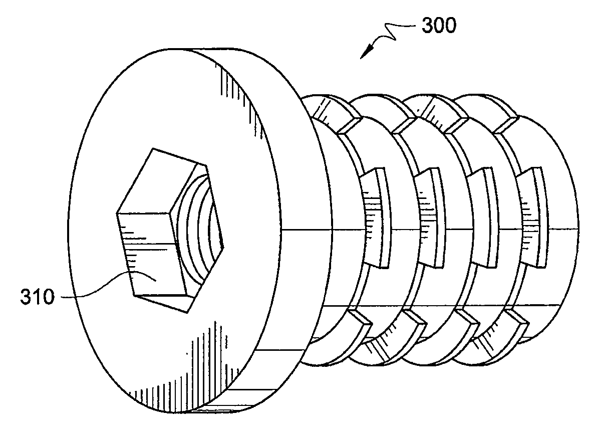
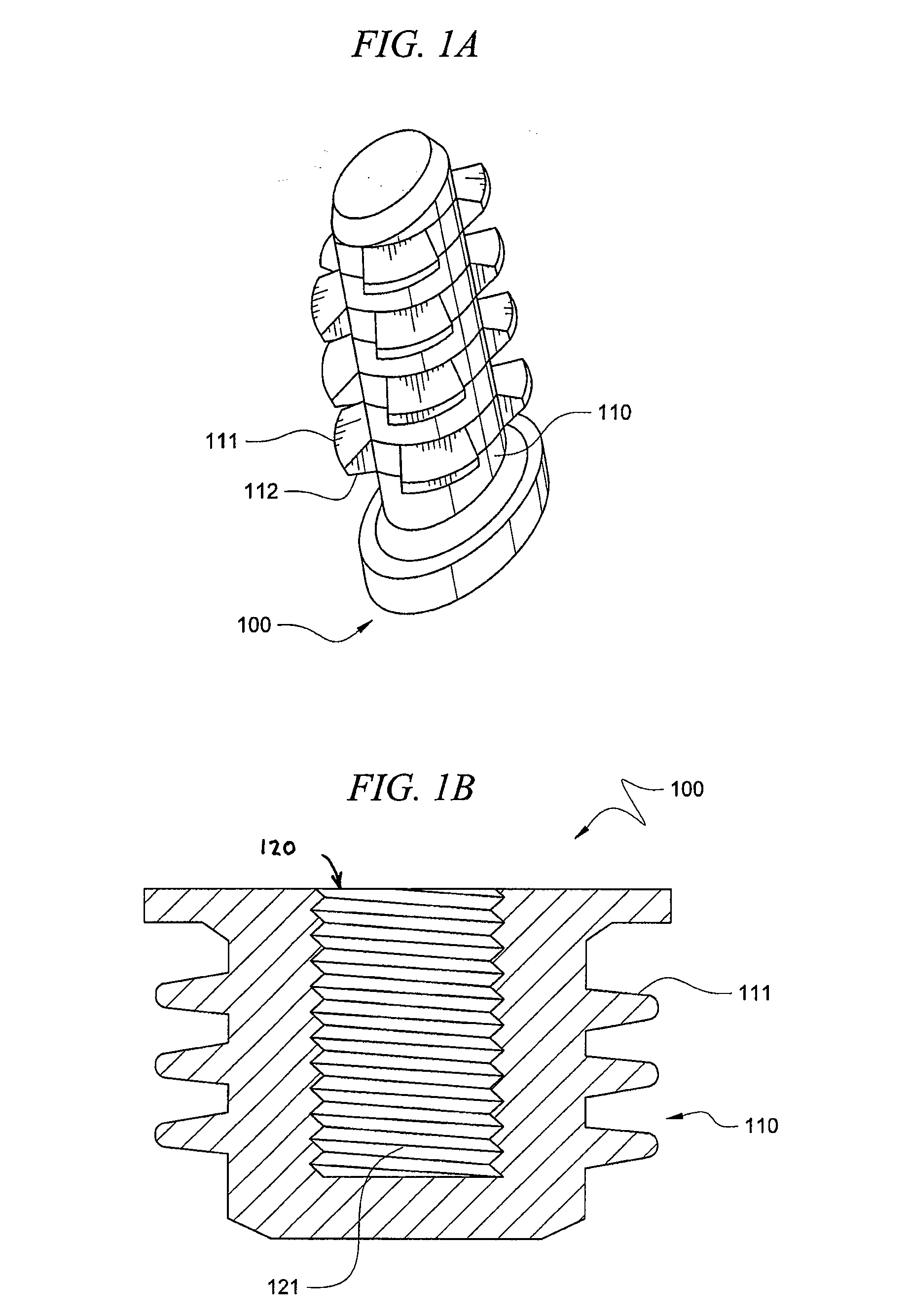
[0014]FIG. 1A is a perspective view of a threaded insert 100 according to at least one embodiment of the present invention. FIG. 1B is a cutaway view of threaded insert 100 according to at least one embodiment. For purposes of this discussion FIGS. 1A and 1B will be discussed together. Threaded insert 100 has an external threaded surface 110 and an internal threaded surface 120. In contrast to previous threaded inserts the external threaded surface 110 is threaded in a direction opposite the direction of threading of the internal threaded surface 120.

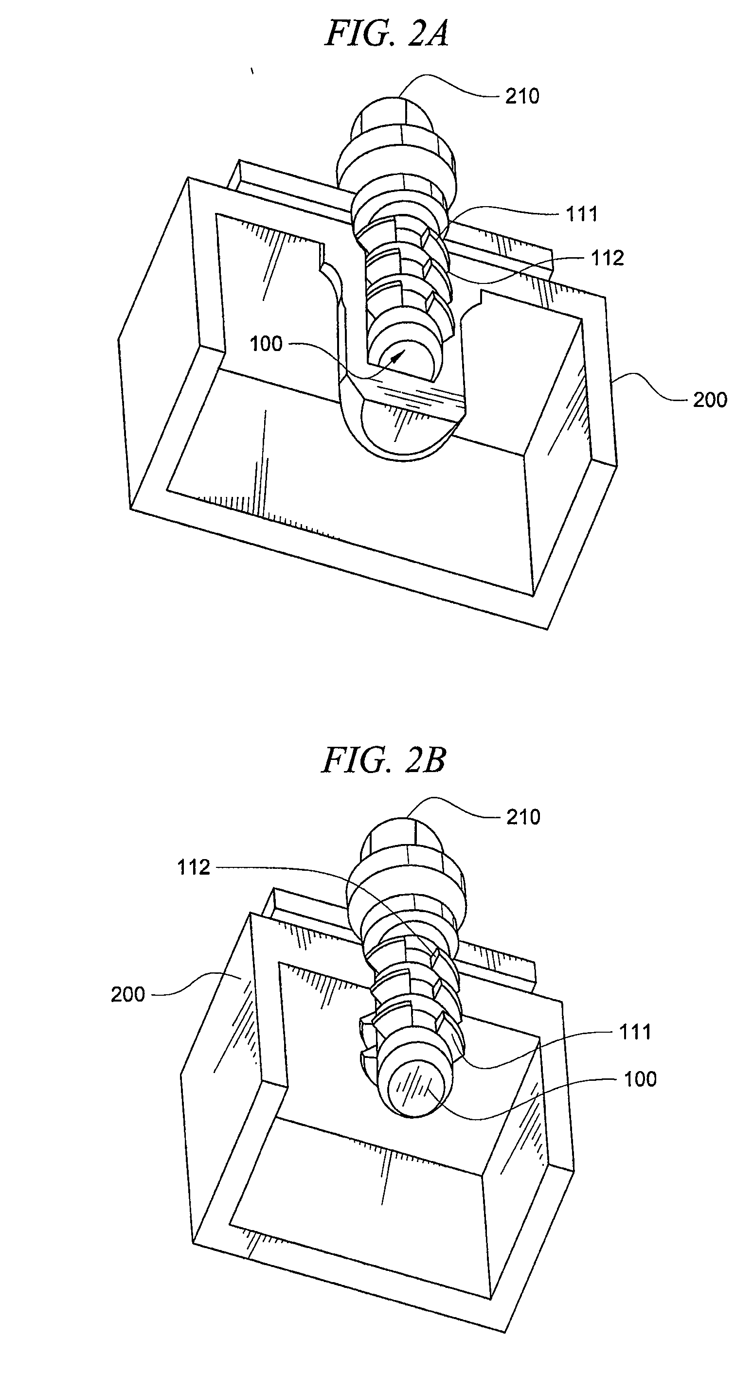
[0015]In one embodiment, insert 100 is placed in a soft material such as plastic or aluminum where the repeated insertion and removal of an item, such as a fastener, directly into the material could damage the material. One embodiment of the design of insert 100 is especially advantageous in environments where corrosion is likely. Further, in one embodiment, insert 100 is formed as a zinc die cast and includes a 96+ hour salt spray corr...


PUM


Abstract

The present invention is directed to a threaded insert having an internal threaded surface and an external threaded surface. The threaded surfaces have threads that are threaded in opposite directions. Thus, if the internal threaded surface is a right handed thread, then the external threaded surface will be a left handed thread. Through the use of the opposite direction threads the insert counteracts torque applied to a threaded fastener as it is inserted or removed. This results in a threaded insert that both resists over tightening of the fastener, and assists in the removal of the fastener from the insert.

Description

TECHNICAL FIELD[0001]This application claims priority under 35 U.S.C. 119(e) from provisional U.S. Patent Application No. 60 / 909,260 filed Mar. 30, 2007, the contents of which are incorporated herein by reference.TECHNICAL FIELD[0002]The present invention relates to threaded inserts for connecting fastening devices to other components. More specifically, the present invention relates to a threaded insert for connecting a fastening device into a component material where corrosion or seizing is likely to occur.BACKGROUND OF THE INVENTION[0003]Threaded inserts are commonly used to provide strength or prevent damage to soft or lightweight materials where a threaded fastener or other item is repeatedly inserted and removed from the material. Threaded inserts are placed in the associated material of a parent part such that the fastener can be inserted into the threaded insert. The threaded insert may be molded directly into the material. However, in other approaches the insert is screwed ...

Claims


Application Information

Patent Timeline
Patent Type & Authority Applications(United States)
IPC IPC(8): F16B37/12F16B23/00F16B25/10F16B39/00F16D1/00G06F19/00
CPCY10T403/75F16B37/125
Inventor WALLING, MARK JOSEPH
Owner TENNANT COMPANY
Why Eureka
Try Eureka