Supercharge Your Innovation With Domain-Expert AI Agents!

Rotor shaft sealing method and structure of oil-free rotary compressor

a technology of rotor shaft and sealing method, which is applied in the direction of machines/engines, rotary/oscillating piston pump components, liquid fuel engines, etc., can solve the problem that oil leaked to the airspace is difficult to escape outsid

Inactive Publication Date: 2008-10-02
ANEST IWATA CORP
View PDF12 Cites 7 Cited by
  • Summary
  • Abstract
  • Description
  • Claims
  • Application Information

AI Technical Summary

Benefits of technology

The present invention provides a method and structure for preventing lubrication oil from entering the compression chamber of an oil-free rotary compressor. The technical effect of the invention is to prevent lubrication oil from entering the compression chamber, even when negative pressure is produced in the chamber. The invention includes a rotor shaft sealing part with two shaft seal means, an annular airspace between the seal means, and a pressurized air supplier to supply pressurized air to the annular airspace. This prevents lubrication oil from leaking into the compression chamber and ensures that lubrication oil does not intrude into the compression chamber. The invention is particularly effective when the compressor is operated at no-load and negative pressure is produced in the compression chamber.

Problems solved by technology

However, with the sealing structure disclosed in the patent literature 1, in a case where leakage of lubrication oil occurs from the bearing part to the airspace through the lip seal, oil leaked to the airspace is difficult to escape outside because of the presence of the check valve in the communicating passage.
Further, in a case where the communicating passage is clogged from any cause, the leaked lubrication oil accumulates in the airspace without being allowed to escape outside, and the leaked lubrication oil accumulated in the airspace is easily ingested into the compression chamber when negative pressure is produced in the compression chamber.
However, a means for allowing lubrication oil leaked into the airspace to escape outside in a convincing way is not disclosed also in the patent literature 2.

Method used


Image

  • Rotor shaft sealing method and structure of oil-free rotary compressor
  • Rotor shaft sealing method and structure of oil-free rotary compressor
  • Rotor shaft sealing method and structure of oil-free rotary compressor

Examples


Embodiment Construction

[0035]A preferred embodiment of the present invention will now be detailed with reference to the accompanying drawings. It is intended, however, that unless particularly specified, dimensions, materials, relative positions and so forth of the constituent parts in the embodiments shall be interpreted as illustrative only not as limitative of the scope of the present invention.

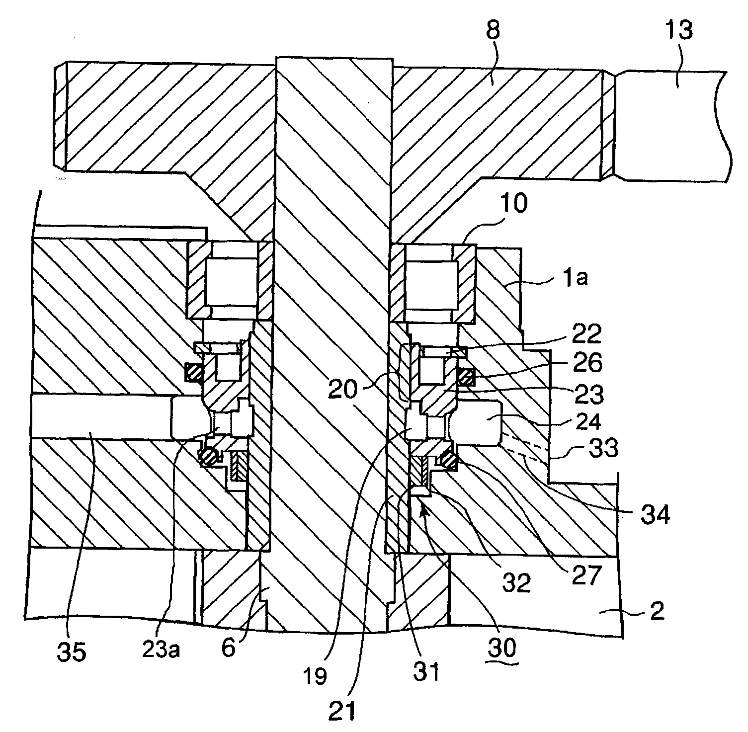
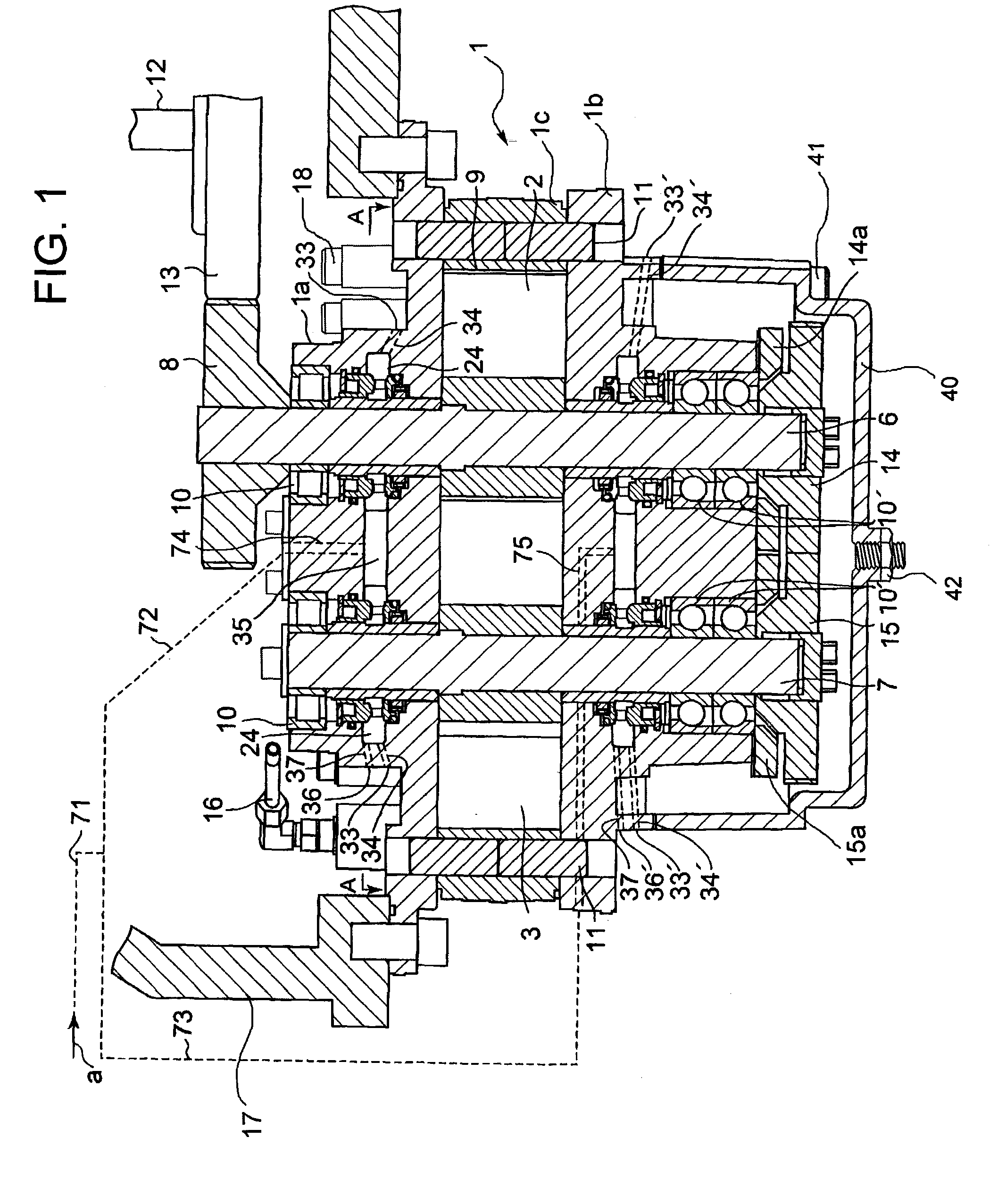
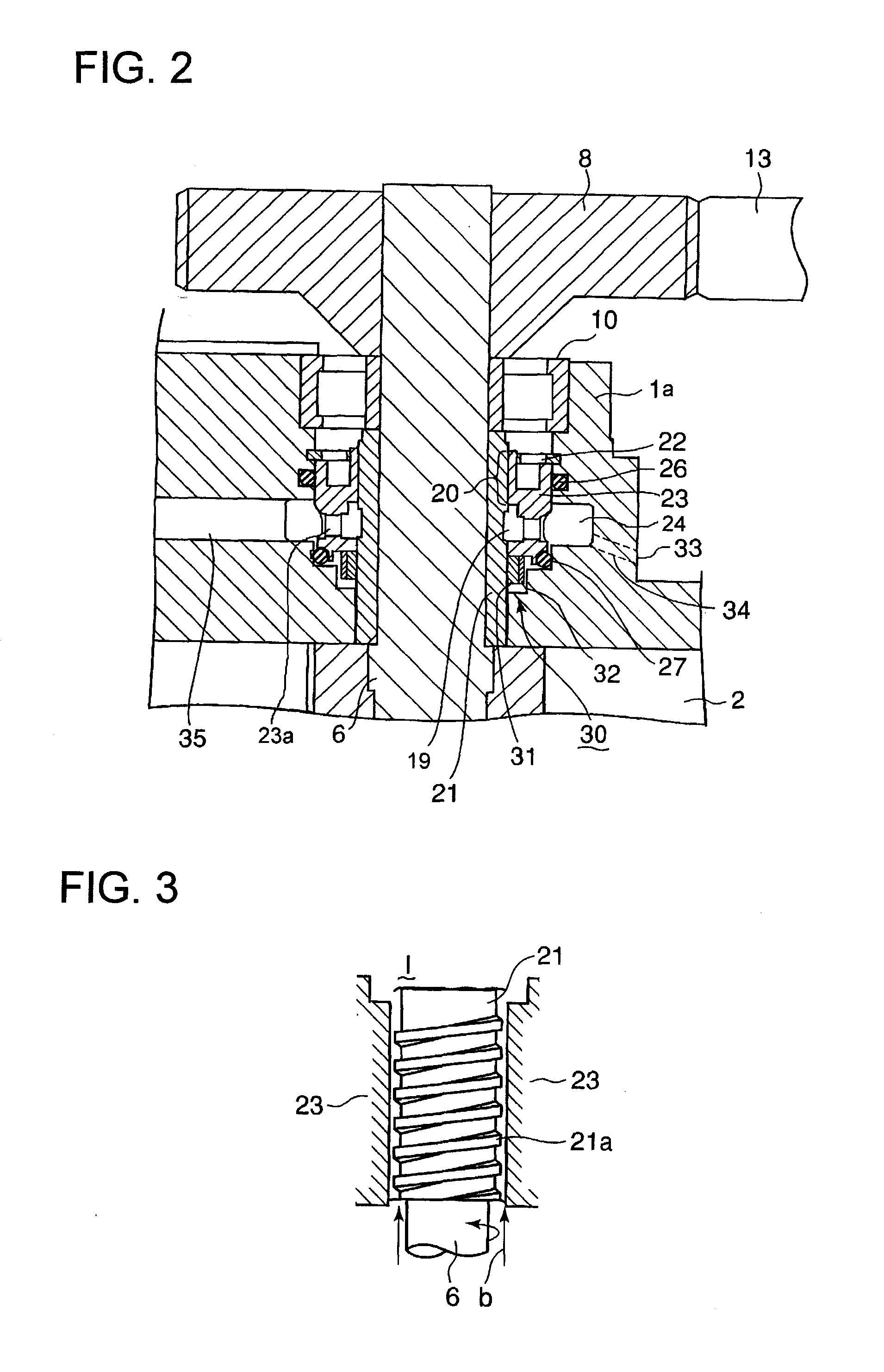
[0036]An embodiment of the invention will be explained with reference to FIGS. 1 to 4. FIG. 1 is a longitudinal sectional view of a tooth type rotary compressor of which rotor shaft sealing structure of the invention is adopted, FIG. 2 is a partially enlarged section of FIG. 1, FIG. 3 is an enlarged sectional view of the viscoseal part of FIG. 1, and FIG. 4 is a sectional view along the line A-A in FIG. 1.

[0037]Referring to FIG. 1, a male rotor 2 and a female rotor 3 are accommodated in a compression chamber 9 formed in a rotor casing 1 which is composed of an upper casing member 1a, a lower casing member 1b, an...


PUM


Abstract

A rotor shaft sealing method for an oil-free rotary compressor is provided, with which occurrence of lubrication oil intrusion into the compression chamber of the compressor which is liable to occur when negative pressure is produced in the compression chamber, is prevented. With a rotor shaft sealing structure composed such that two shaft seal means (20,31) are provided in the rotor casing (1) between the oil lubricated bearing (10, 10′) and the compression chamber (9) such that an annular airspace (24) is formed between the two shaft seal means (20,31), at least one communicating hole (34,34′) is provided to communicate the annular airspace (24) to the outside of the rotor casing (1), and the annular airspace (24) of the male rotor shaft (6) sealing part and the annular airspace (24) of the female rotor shaft (7) sealing part are connected by a between-rotor shaft communication passage (35), pressurized air is supplied to the annular airspaces (24) by which lubrication oil intrusion into the compression chamber (9) is prevented.

Description

BACKGROUND OF THE INVENTION[0001]1. Field of the Invention[0002]The present invention relates to a rotor shaft sealing method and structure of an oil-free rotary compressor such as a tooth type rotary compressor, whose sealing structure can prevent lubrication oil of the drive mechanism of the rotor from leaking into the compression chamber of the compressor even when the pressure of the compression chamber becomes lower than atmospheric pressure, which occurs under some operation condition of the compressor.[0003]2. Description of the Related Art[0004]Generally, a tooth type rotary compressor consists of two rotors, a male rotor and a female rotor, each having claw-like teeth, or lobes. The rotors turn in opposite directions without contact to each other to compress gas trapped in the compression pockets formed between the lobes and inner surface of a compressor casing as the rotors rotate. As the rotors do not contact with each other and with the inner surface of the compressor ca...

Claims


Application Information

Patent Timeline
Patent Type & Authority Applications(United States)
IPC IPC(8): F04C27/00F01D11/04F16J15/16
CPCF04C18/123F04C23/001F04C27/009F04C2220/12
Inventor KIMURA, HIDEYUKIMUTO, MASAMI
Owner ANEST IWATA CORP
Features
  • R&D
  • Intellectual Property
  • Life Sciences
  • Materials
  • Tech Scout
  • Unparalleled Data Quality
  • Higher Quality Content
  • 60% Fewer Hallucinations
Learn More