Imprinting jig and imprinting apparatus

a technology of imprinting jig and imprinting apparatus, which is applied in the direction of dough shaping, manufacturing tools, instruments, etc., can solve the problems of sheet deformation, pattern may not be accurately transferred onto the sheet, and the whole sheet may not be uniformly pressed, so as to reduce the adhesion between the stamper holder and the elastic member, and reduce the effect of separation

Inactive Publication Date: 2008-10-02
HITACHT MAXELL LTD
View PDF6 Cites 11 Cited by
  • Summary
  • Abstract
  • Description
  • Claims
  • Application Information

AI Technical Summary

Benefits of technology

[0017]According to an embodiment of the invention, the adhesion reducing means may comprise irregularity formed on a surface of the stamper holder on the elastic member side. A height of the irregularity may be approximately 1 μm. In this case, the surface of the stamper holder is roughened so that irregularity having a height of e.g. approximately 1 μm is formed, thereby adhesion between the stamper holder and the elastic member may be reduced, and further, the plastic sheet may be easily separated from the stamper.
[0018]According to an embodiment of the invention, the adhesion reducing means may comprise irregularity formed on a surface of the elastic member on the stamper side. A height of the irregularity may be approximately 1 μm. In this case, the surface of the elastic member is roughened so that irregularity having a height of e.g.

Problems solved by technology

If these are pressed in a non-parallel state, the whole sheet may not be uniformly pressed, and the pattern may not be accurately transferred onto the sheet, or the sheet may be deformed.
That is, in cooling and separating step after transferring the pattern, a very large force is necessary to separate the already-transferred sheet from the stamper of the imprinting jig, when using the rubber sheet for buffering.
Furthermore, if the already-transferred sheet is separated from the stamper at a tilt angle

Method used


Image

  • Imprinting jig and imprinting apparatus
  • Imprinting jig and imprinting apparatus
  • Imprinting jig and imprinting apparatus

Examples


Embodiment Construction

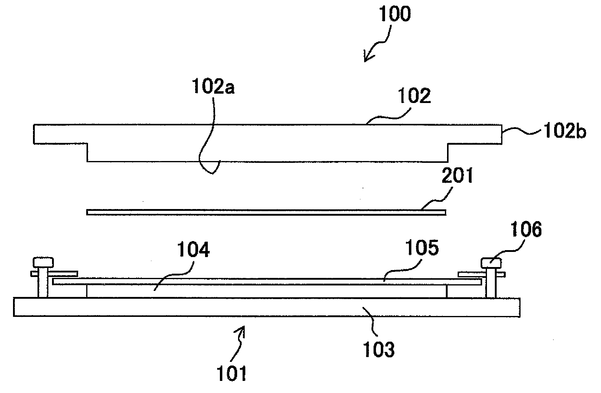
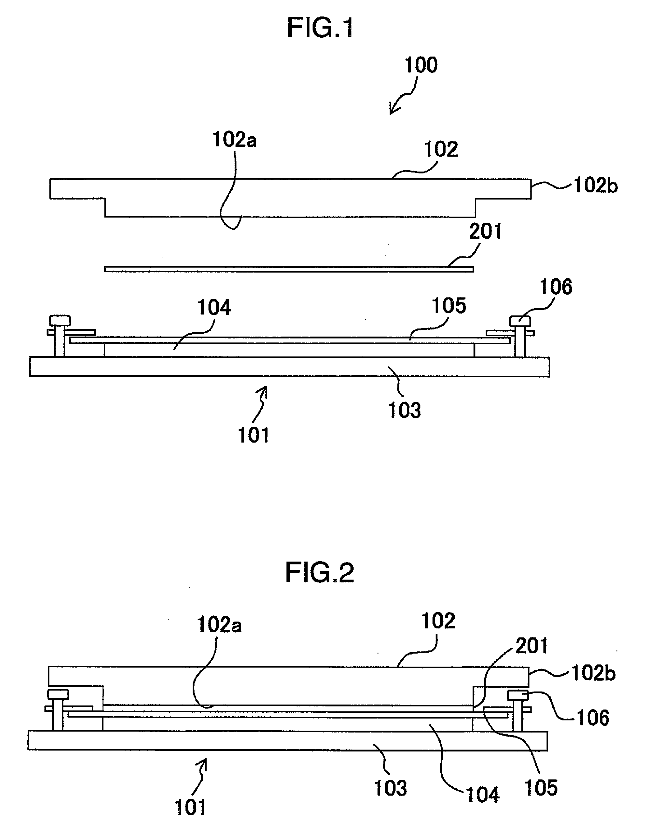
[0031]An embodiment of an imprinting jig according to the invention will be described with reference to FIG. 1. As shown in FIG. 1, an imprinting jig 100 mainly includes a stamper holder assembly 101, and a mirror plate 102 placed above the stamper holder assembly 101.

[0032]The mirror plate 102 is a substantially disk-shaped member made of stainless steel. A lower surface 102a of the mirror plate 102 facing the stamper holder assembly 101 is mirror finished. A flange 102b is provided around the periphery of the mirror plate 102. The flange has a smaller thickness than that of the central portion of the mirror plate 102. In handling the mirror plate 102, flange 102b may be gripped to prevent a careless contact with the mirror-finished lower surface 102a.

[0033]The stamper holder assembly 101 includes: a holder plate 103 that is a substantially disk-shaped member made of stainless steel; a rubber sheet 104 or an elastic member, made of heat-resisting rubber, placed on an upper surface...


PUM

PropertyMeasurementUnit
Heightaaaaaaaaaa
Adhesion strengthaaaaaaaaaa
Thermal resistanceaaaaaaaaaa

Abstract

The invention provides an imprinting jig for transferring a pattern onto a thermoplastic sheet. The imprinting jig is provided with: a first die having a surface with a pattern; a die holder for supporting the first die; an elastic member placed between the first die and the die holder; and a second die opposing to the first die. The thermoplastic sheet is placed on the surface with the pattern of the first die. The imprinting jig optionally includes an adhesion reducing means between the elastic member and the first die or between the elastic member and the die holder.

Description

BACKGROUND OF THE INVENTION[0001](1) Field of the Invention[0002]The invention relates to an imprinting jig for putting a thermoplastic sheet therebetween and an imprinting apparatus. Particularly it relates to the imprinting jig and apparatus used for a thermal imprinting process for transferring or printing a fine pattern onto the thermoplastic sheet by heating and applying pressure.[0003](2) Related Art[0004]Professor Stephen Y. Chou et al. of, Princeton University have made a number of reports on a nano-imprinting process which prints a fine pattern having a high aspect ratio at a moderate price. The nano-imprinting process includes mainly an optical nano-imprinting process in which ultraviolet curing resin is used for printing a pattern, and a thermal nano-imprinting process in which heat and pressure are applied to a thermoplastic substance to print a pattern. Especially the latter process has been attracting attention since the process can produce flat panel displays, electro...

Claims


Application Information

Patent Timeline
IPC IPC(8): B29C59/00
CPCB29C37/0003B29C59/022B29C2059/023B29L2017/005G11B7/263
Inventor KISHI, HIROYUKIYAMANAKA, HIDEAKI
Owner HITACHT MAXELL LTD
Why Eureka
Try Eureka