Eureka AIR delivers breakthrough ideas for toughest innovation challenges, trusted by R&D personnel around the world.

Nonaqueous electrolytic solution secondary battery and method for preparing the same

a secondary battery and nonaqueous electrolytic technology, which is applied in the direction of cell components, sustainable manufacturing/processing, final product manufacturing, etc., can solve the problems of battery also having a problem of infiltrating the electrolytic solution uniformly, discordance of layers, and extreme long injecting time, so as to achieve the effect of shortening the injecting time of the electrolytic solution

Inactive Publication Date: 2008-10-02
SHARP KK
View PDF2 Cites 9 Cited by
  • Summary
  • Abstract
  • Description
  • Claims
  • Application Information

AI Technical Summary

Benefits of technology

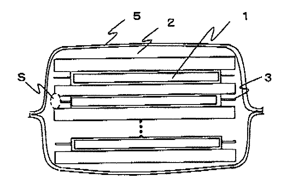
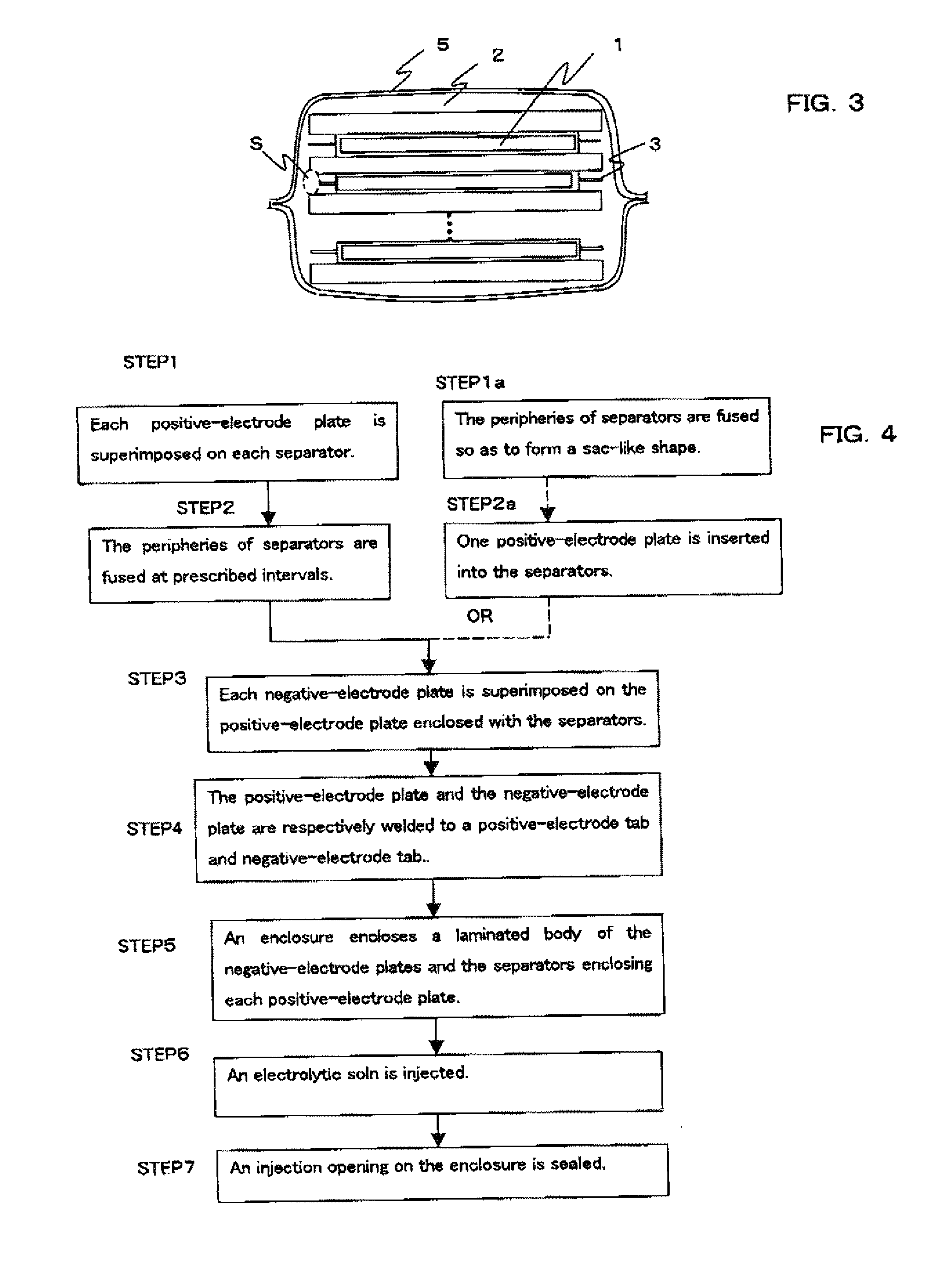
[0012]The present invention is to solve the above-mentioned problems, and has an object of providing a secondary battery that is capable of shortening injecting time for injecting an electrolytic solution, and infiltrating the electrolytic solution uniformly, during a process for preparing the secondary battery. Also, the present invention has another object of providing the secondary battery in which discordance of layers of positive-electrode plates, negative-electrode plates, and separators does not easily occur during a process for laminating them and the following process.
[0015]Since the electrolytic solution is injected through the injection pathway according to a structure described above, the injecting time for injecting the electrolytic solution can be shortened.

Problems solved by technology

A large-scale nonaqueous electrolytic solution secondary battery has a problem with injecting time for injecting the electrolytic solution during a process for injecting the electrolytic solution between a positive-electrode plate and a negative-electrode plate, due to large areas of the electrode plates, and also has a problem with discordance of layers during a process for laminating the electrode plates.
However, the large-scale nonaqueous electrolytic solution secondary battery has extremely long injecting time for injecting the electrolytic solution, and has a problem with a process for preparing the battery.
The large-scale nonaqueous electrolytic solution secondary battery also has a problem of infiltrating the electrolytic solution uniformly.
Further, since the large-scale nonaqueous electrolytic solution secondary battery is necessary to have a plurality of positive-electrode plates, negative-electrode plates, and separators, which are laminated, each being large in size, the discordance of the layers during the process for laminating the positive-electrode plates, the negative-electrode plates, and the separators easily occurs, due to large areas thereof.

Method used


Image

  • Nonaqueous electrolytic solution secondary battery and method for preparing the same
  • Nonaqueous electrolytic solution secondary battery and method for preparing the same
  • Nonaqueous electrolytic solution secondary battery and method for preparing the same

Examples


example 1

[0085]In a process for preparing a positive-electrode plate, N-methyl-2-pyrrolidone (NMP) as a solvent is added to a mixture of a positive active material containing 100 parts by weight of LiMn 204, a conductive material containing 5 parts by weight of acetylene black, and a binder containing 5 parts by weight of PVdF, and the solution is mixed by use of a planetary mixer so as to prepare a positive-electrode paste The prepared paste is uniformly applied on both sides of a belt-like aluminum film which is a positive current collector and has a thickness of 20 μm, by use of a coating device, except a section where is to be uncoated. The aluminum film coated with the paste is dried under reduced pressure at 130° C. for 8 hours, and then pressurized by use of a hydraulic press. The positive-electrode plate is prepared as described above, and is cut to a prescribed size. As a result, the positive-electrode plate having 252 mm in width, 320 mm in length, and 80 μm in thickness is prepare...

example 2

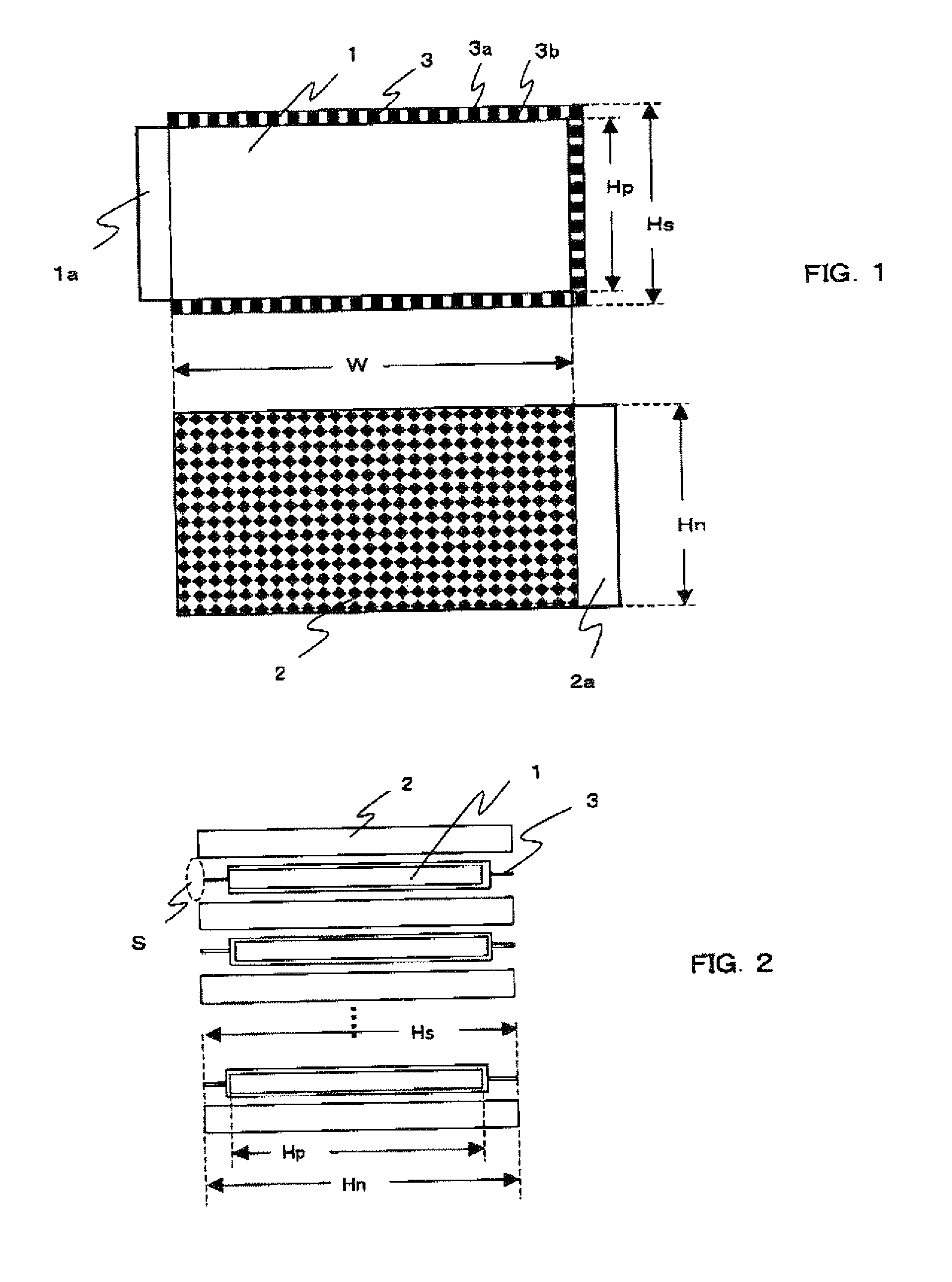
[0092]In Example 2, two separators are cut to a width of 256 mm, and a negative-electrode plate is cut to a width of 256 mm. A positive-electrode plate having the same size as that of Example 1 is sandwiched between the two separators. A total length of the separators, which protrude in the direction of the shorter sides (width) of the positive-electrode plate, is set to be 4 mm. A secondary battery is prepared through the same procedure as that in Example 1 except the total length above.

example 3

[0093]In Example 3, two separators are cut to a width of 262 mm, and a negative-electrode plate is cut to a width of 262 mm. A positive-electrode plate having the same size as that of Example 1 is sandwiched between the two separators. A total length of the separators, which protrude in the direction of the shorter sides (width) of the positive-electrode plate, is set to be 10 mm. A secondary battery is prepared through the same procedure as that in Example 1 except the total length above.


PUM

PropertyMeasurementUnit
lengthaaaaaaaaaa
lengthaaaaaaaaaa
lengthaaaaaaaaaa

Abstract

To provide a secondary battery that is capable of shortening injecting time for injecting an electrolytic solution, and infiltrating the electrolytic solution uniformly, during a process for preparing the secondary battery. Also, to provide the secondary battery in which discordance of layers of positive-electrode plates, negative-electrode plates, and separators does not easily occur during a process for laminating them and the following process.A nonaqueous electrolytic solution secondary battery of the present invention comprises: negative-electrode plates which are rectangular; positive-electrode plates which each have a pair of opposed sides shorter than a pair of opposed sides of each negative-electrode plate; separators which each are formed of a porous resin film enclosing each positive-electrode plate; an enclosure which encloses the negative-electrode plates and separators which are laminated alternately, in which a direction of the sides of the negative-electrode plates aligns with a direction of the shorter sides of the positive-electrode plates; and an injection pathway for the nonaqueous electrolytic solution, which the pathway being formed between the negative-electrode plates between which the separator is sandwiched, the pathway being formed at edges of opposed sides of the negative-electrode plates.

Description

CROSS-REFERENCE TO RELATED APPLICATION[0001]This application is related to Japanese Patent Application No. 2007-88214 filed on Mar. 29, 2007, whose priority is claimed under 35 USC §119, the disclosure of which is incorporated by reference in its entirety.BACKGROUND OF THE INVENTION[0002]1. Field of the Invention[0003]The present invention relates to a nonaqueous electrolytic solution secondary battery in which positive-electrode plates, separators, and negative-electrode plates are laminated, and a method for preparing the battery. More specifically, the present invention relates to a large-scale nonaqueous electrolytic solution secondary battery and a method for preparing the large-scale battery.[0004]2. Description of the Related Art[0005]A large-scale nonaqueous electrolytic solution secondary battery has a problem with injecting time for injecting the electrolytic solution during a process for injecting the electrolytic solution between a positive-electrode plate and a negative...

Claims


Application Information

Patent Timeline
Patent Type & Authority Applications(United States)
IPC IPC(8): H01M2/02H01M10/36H01M4/13H01M10/0566H01M10/0585H01M50/129H01M50/414H01M50/627
CPCH01M2/0267H01M2/0275Y02E60/122H01M2/361H01M10/052H01M2/1653Y02E60/10Y02P70/50H01M50/129H01M50/627H01M50/414
Inventor UTSUMI, HISAYUKINISHIJIMA, MOTOAKIKOBAYASHI, SHINSUKE
Owner SHARP KK
Why Eureka
Eureka Blog
Learn More