Handle for a pan or a similar kitchen vessel

Active Publication Date: 2008-10-09
BALLARINI PAOLO E FILI SPA
View PDF2 Cites 6 Cited by
  • Summary
  • Abstract
  • Description
  • Claims
  • Application Information

AI Technical Summary

Benefits of technology

[0010]Accordingly, the object of the present invention is to overcome the above mentioned prior art drawbacks by providing a handle for a pan or similar kitchen vessel having all the advantages of a silicone resin handle, which can be made in a very inexpensive manner, has a small weight and a very high mechanical and thermal stress resistance.

Problems solved by technology

Such a steel tube handle, however, has the drawback that, during the cooking operation, the handle can be excessively heated, thereby it is necessary to provide between the pan body and handle thermally insulating means, which make the assembling of the handle more complex and expensive.
In another prior pan handle, the handle metal core, integral with the pan, is coated by wood insulating elements: however, this approach has been found as insufficiently practical, since the wood coating is affected, upon a continued use, by the heat source and the required washing and cleaning operations, causing, upon a prolonged period of use, the handle to be partially destroyed.
To provide such a synthetic material handle, the metal core is coated, in an overmolding method, by a synthetic material, which is a slow, expensive and complex making procedure.
Also known is the fact that a pan handle integrally made of a silicone is commercially unsupportable, just due to the very high cost of the silicone resin and the processing methods therefor.

Method used


Image

  • Handle for a pan or a similar kitchen vessel
  • Handle for a pan or a similar kitchen vessel
  • Handle for a pan or a similar kitchen vessel

Examples


Embodiment Construction

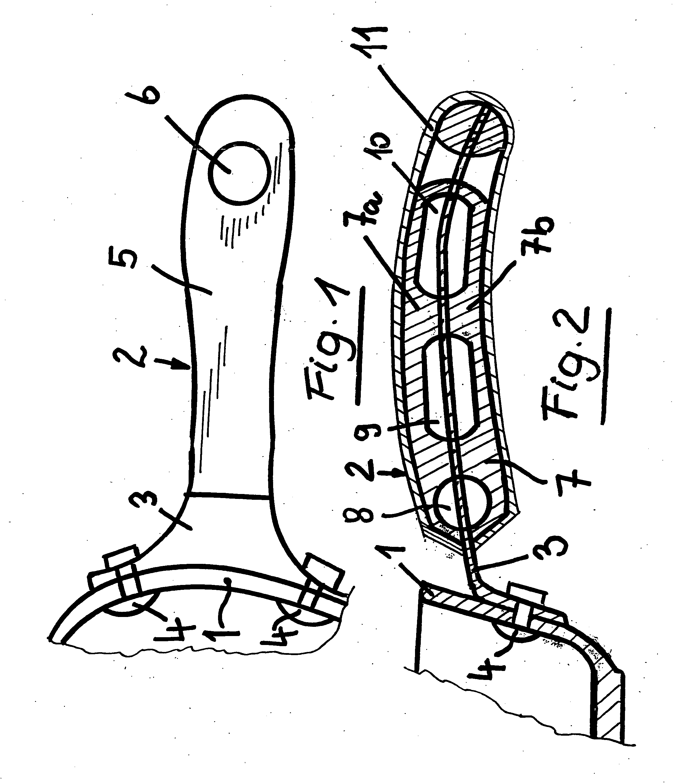
[0017]As is shown in FIG. 1, a pan 1 comprises a handle 2 coupled thereto.

[0018]Said handle 2 comprises a handle core made of a thin sheet metal, the core 3 being fixedly coupled, by coupling rivets 4, to the body of the pan 1.

[0019]As is clearly shown in FIG. 2, the core 3 of the handle 2 comprises a sheet metal element, radially projecting from the body of the pan 1 and being coupled by said coupling rivets 4, or other suitable coupling means, to the body of the pan 1.

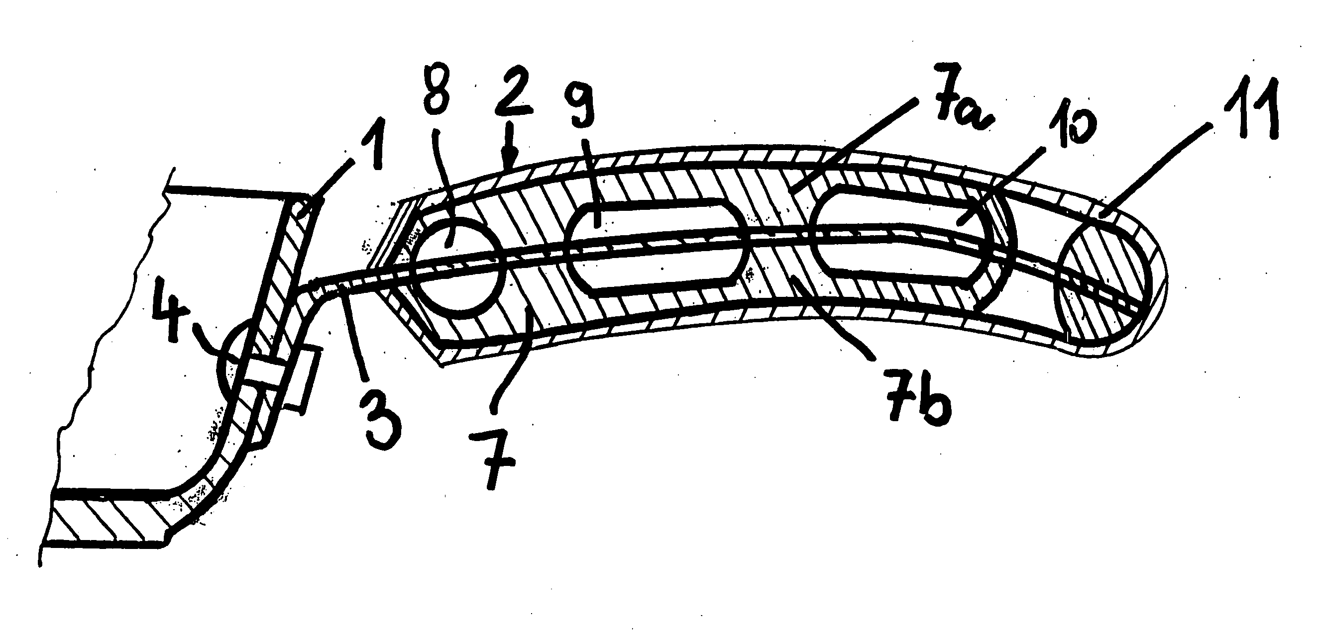
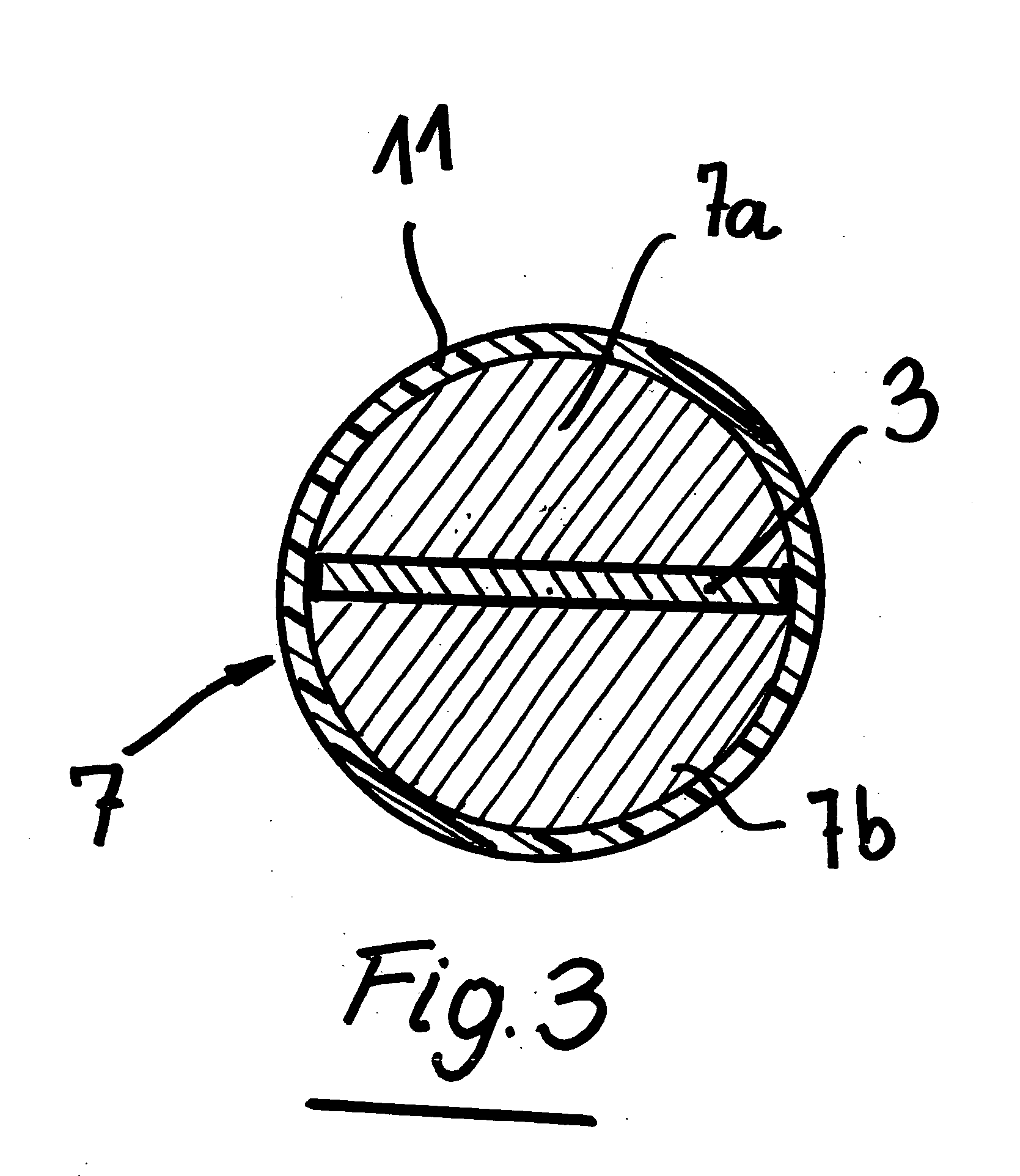
[0020]The sheet metal core 3 is enclosed by a reinforcement body, generally indicated by 7, said body 7 being made of a very inexpensive heat resistant and easily machinable material.

[0021]In particular, said body 7 can comprise a single body applied on the core 3 by injecting a suitable injection material or it can be made of two parts 7a and 7b which may be glued to one another or assembled along mutual contacting surfaces by mechanical coupling means 21, 22, by forming, for example, suitable openings 22 through on...


PUM


Abstract

A handle for a pan or a similar kitchen vessel comprises a handle supporting core integral with the pan body and combined by two reinforcement half-bodies made of a heat resistant material, the pan handle including reinforcement half bodies being coated by a silicone resin coating sheath.

Description

BACKGROUND OF THE INVENTION[0001]The present invention relates to a handle for a pan or a similar kitchen vessel.[0002]Several pan handles are known from the prior art.[0003]Thus, for example, a pan handle comprising a steel tube is already known in the art.[0004]Such a steel tube handle, however, has the drawback that, during the cooking operation, the handle can be excessively heated, thereby it is necessary to provide between the pan body and handle thermally insulating means, which make the assembling of the handle more complex and expensive.[0005]In another prior pan handle, the handle metal core, integral with the pan, is coated by wood insulating elements: however, this approach has been found as insufficiently practical, since the wood coating is affected, upon a continued use, by the heat source and the required washing and cleaning operations, causing, upon a prolonged period of use, the handle to be partially destroyed.[0006]Yet another approach provides to coat the pan h...

Claims


Application Information

Patent Timeline
IPC IPC(8): B65D25/28B25G1/00A47J27/00
CPCA47J45/061Y10T16/44Y10T16/4707A47J45/08
Inventor FERRON, JACOPO
Owner BALLARINI PAOLO E FILI SPA
Why Eureka
Try Eureka