Vibration damper

Active Publication Date: 2008-10-09
PARKER INTANGIBLES LLC
View PDF17 Cites 2 Cited by
  • Summary
  • Abstract
  • Description
  • Claims
  • Application Information

AI Technical Summary

Benefits of technology

[0011]The present invention provides fuel injector assemblies with frictionally damped fuel supply members, including fuel feed strips. More particularly, the invention provides friction dampers and/or assemblies that frictionally damp movement of fuel supply members in at least one direction as a function of frequency. Accordingly, the invention provides a friction damper that allows low fr

Problems solved by technology

This difference in thermal expansion can result in undesirable stresses being placed on the fuel feed strip and/or stem.
High cycle fatigue generally occurs when resonance or vibration modes are excited by driving frequencies inherent in the operation of the engine.
However, such devices can be complex and require additional parts which can resonate themselves.
Further, many such devices must be installed prior to assembly of the fuel injector and are not easily serviced.
Some designs can restrict movement of the fuel feed strip in response to thermal expansion of the stem and/or strip and thereby induc

Method used


Image

  • Vibration damper
  • Vibration damper
  • Vibration damper

Examples


Embodiment Construction

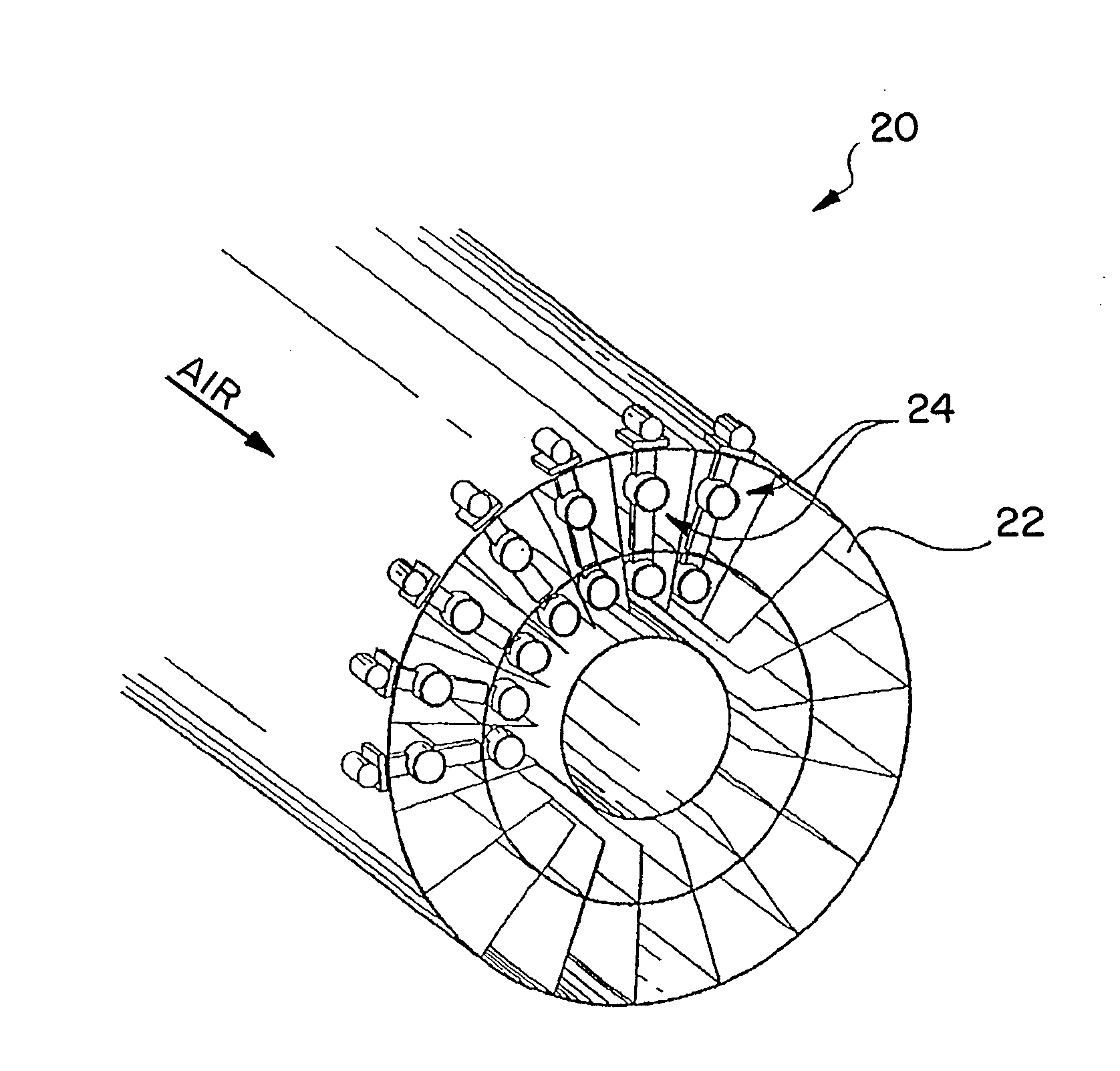
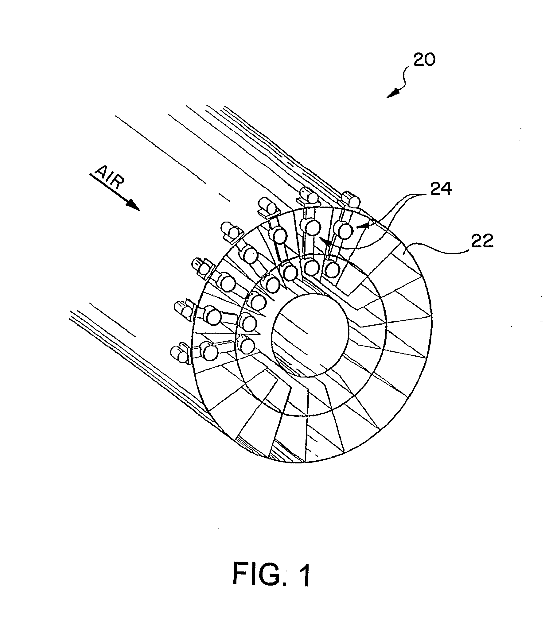
[0027]Referring to the drawings and initially to FIG. 1, a portion of a known combustion engine is indicated generally at 20. The upstream, front wall of a dual combustion chamber for the engine is shown at 22, and a plurality of fuel injectors, for example as indicated generally at 24, are shown supported within the combustion chamber. The fuel injectors 24 atomize and direct fuel into the combustion chamber 22 for burning. Combustion chamber 22 can be any useful type of combustion chamber, such as a combustion chamber for a gas turbine combustion engine of an aircraft, however, the present invention is believed useful for combustion chambers for any type of combustion application, such as in land vehicles. In any case, the combustion chamber will not be described herein for sake of brevity, with the exception that as should be known to those skilled in the art, air at elevated temperatures (up to 1300.degree. F. in the combustion chamber of an aircraft), is directed into the combu...


PUM


Abstract

Fuel injector assemblies with frictionally damped fuel supply members, including fuel feed strips. More particularly, the invention provides friction dampers and/or assemblies that frictionally damp movement of fuel supply members in at least one direction as a function of frequency. Accordingly, low frequency vibration can be undamped, while vibration above a prescribed frequency can be damped. Some of the embodiments provide a friction damper that is easily serviceable, and can be installed after final assembly of a fuel injector. Aspects of the invention are applicable to other components of fuel injectors and gas turbine engines in addition to fuel supply members.

Description

RELATED APPLICATION[0001]This application claims the benefit of U.S. Provisional Application No. 60 / 826,934 filed Sep. 26, 2006, which is hereby incorporated herein by reference.FIELD OF THE INVENTION[0002]The present invention relates generally to fuel injectors. More particularly, the invention relates to fuel injectors for use with gas turbine combustion engines.BACKGROUND OF THE INVENTION[0003]A gas turbine engine contains a compressor in fluid communication with a combustion system that often contains a plurality of combustors. The compressor raises the pressure of the air passing through each stage of the compressor and directs it to the combustors where fuel is injected and mixed with the compressed air. The fuel and air mixture ignites and combusts creating a flow of hot gases that are then directed into the turbine. The hot gases drive the turbine, which in turn drives the compressor, and for electrical generation purposes, can also drive a generator.[0004]Most combustion s...

Claims


Application Information

Patent Timeline
IPC IPC(8): F02M61/18
CPCF02M55/00F02M2200/315
Inventor BISHARA, FADYLEHTINEN, JEFFREY
Owner PARKER INTANGIBLES LLC
Why Eureka
Try Eureka